Pressure welding device with a measuring device, measuring in a contactless manner, for detecting the surface quality, the true running and/or the axial runout in a front welding area

a technology of pressure welding and measuring device, which is applied in the direction of welding auxiliary device, domestic articles, application, etc., can solve the problem of possible increase of for

Active Publication Date: 2018-07-24
KUKA SYSTEMS
View PDF15 Cites 0 Cited by
  • Summary
  • Abstract
  • Description
  • Claims
  • Application Information

AI Technical Summary

Benefits of technology

[0006]The pressure welding technique, and especially friction welding technique, according to the present invention makes is possible to obtain a high-quality, reproducible and loadable weld joint. It makes it possible to achieve a certain minimum quality of the surface quality and / or the axial runout and / or radial runout and / or true running and / or concentricity of the workpiece parts in relation to the axis of rotation. Consequently, it is possible to prevent the workpiece parts from possibly not contacting all over and a partial and / or nonuniform plasticizing and thus formation of a low-quality weld joint from occurring.
[0007]The pressure welding technique according to the present invention manages on a low design and control effort and a simplified kinematics. The, e.g., rotating device, which is present anyway, on one or on both adjacent clamping devices can be used for the metrological detection of the surface quality and / or the axial runout and / or true running of the front of one or both workpiece parts to be welded. A preferably contactless sensor detection, especially using a measuring beam is especially accurate, simple and reliable.
[0008]The pressure welding technique according to the present invention allows an automated checking of the workpiece parts to be welded and the automatic process sequences affected hereby. Corrections of defects can be eliminated within the pressure welding device by changing the position of and / or remachining of a workpiece part. The pressure welding device can be automated in its welding process, which may also include an automatic loading and unloading of the workpiece parts or welded workpieces as well as possibly a discharging of defective workpiece parts. Furthermore, the finished welded part may also be checked, e.g., with regard to the true running and / or axial runout of the part end or part ends.
[0011]A detection of the surface quality and / or of the axial runout and / or true running can be carried out with a measuring device, and especially a first measuring device on the second workpiece part in relation to the axis of rotation, while the second workpiece part is already clamped for producing the friction weld joint, i.e., in the clamped position provided for the welding. For the carrying out of a measurement, the first measuring device can be rotated about the axis of rotation, especially by means of a rotation of the first clamping device, and thereby measure the welding area of the second workpiece part. The first measuring device is preferably arranged permanently on the pressure welding device or friction welding device, especially on the first clamping device, such that it does not have to be removed for carrying out the welding. As a result of this, the surface quality and / or the true running and / or axial runout can advantageously be detected without loss of cycle time.
[0012]The first measuring device preferably has a separate power supply, which is connected with the first measuring device and is also mounted rotatably about the axis of rotation, and especially fastened to the first clamping device. By means of the power supply, the measuring device can be operated during a measurement process, without a cabling being required for the feed of power between the stationary machine frame and the rotatably mounted measuring device.
[0015]In a pressure welding device or friction welding device with a first and a second measuring device of the type mentioned above, a measuring of both workpiece parts can advantageously be carried out without loss of cycle time in an automated and parallelized process. Especially a simultaneous measuring of the two workpiece parts can be carried out, whereby the first clamping device is rotated in a controlled manner and brings about the relative movement between workpiece part and measuring device for both measurement processes in each case.

Problems solved by technology

The workpiece parts are plasticized in their welding areas by means of contact in the front and rotating friction under pressure and then connected with possibly increased force in an upsetting stroke.

Method used


Image

  • Pressure welding device with a measuring device, measuring in a contactless manner, for detecting the surface quality, the true running and/or the axial runout in a front welding area
  • Pressure welding device with a measuring device, measuring in a contactless manner, for detecting the surface quality, the true running and/or the axial runout in a front welding area
  • Pressure welding device with a measuring device, measuring in a contactless manner, for detecting the surface quality, the true running and/or the axial runout in a front welding area

Examples


Embodiment Construction

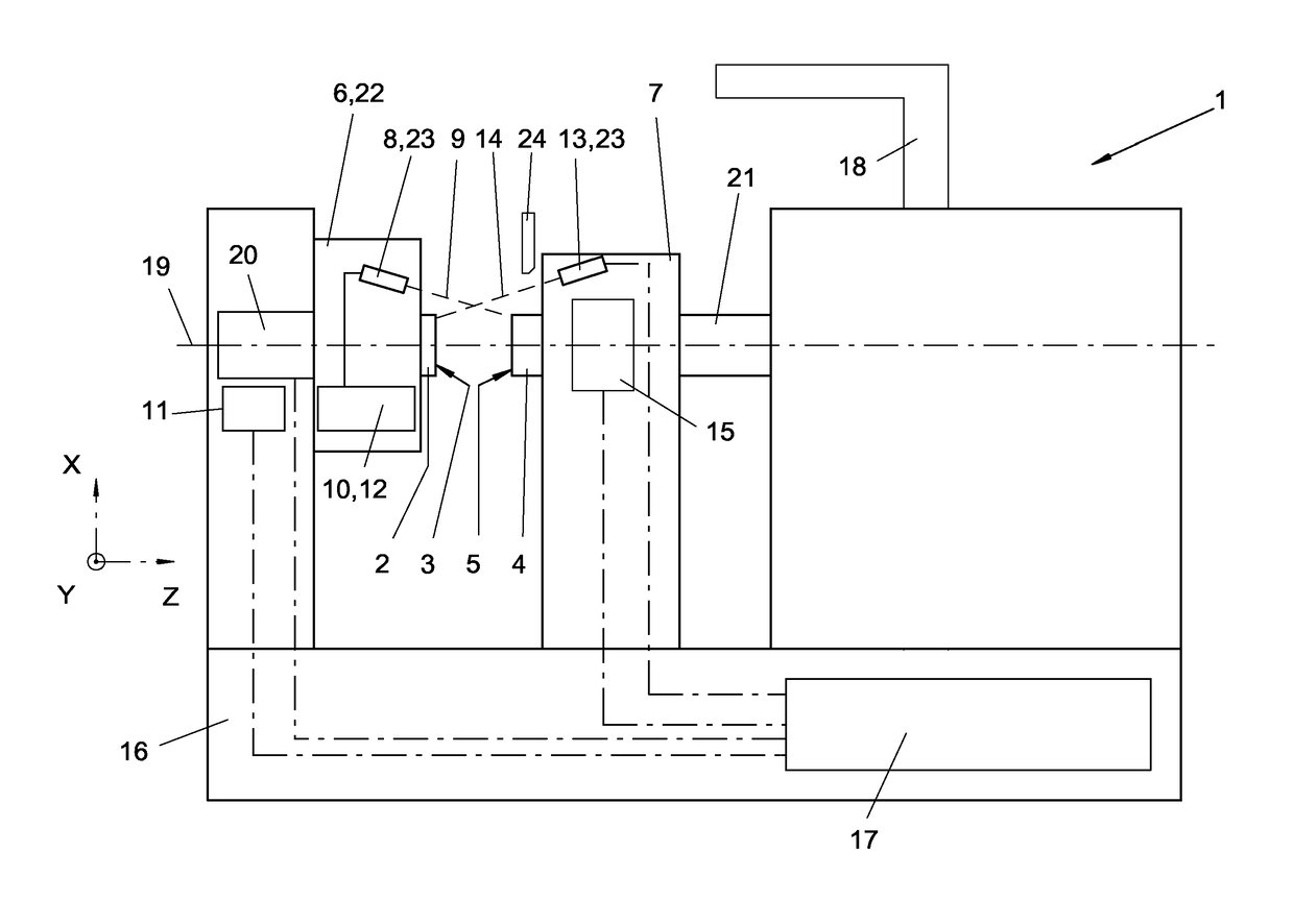
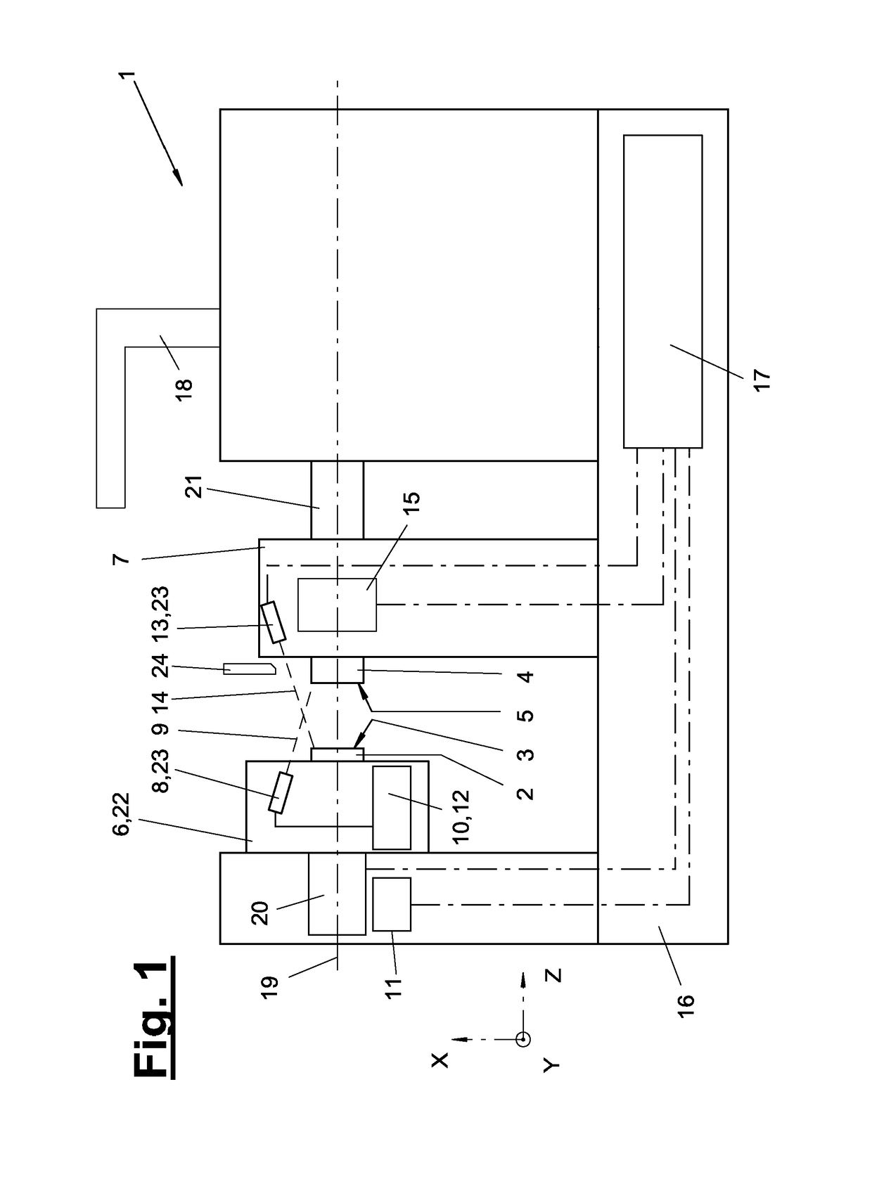
[0034]The present invention pertains to a pressure welding device, preferably a friction welding device (1), and a method for producing a weld joint between a first workpiece part (2) and a second workpiece part (4). Such a friction welding device (1) for two workpiece parts (2, 4) is schematically shown in FIG. 1. In an alternative, not shown, the pressure welding device (1) may operate with a magnetically moved electric arc.

[0035]The first workpiece part (2) and the second workpiece part (4) may consist of any materials, and especially of iron-containing or non-iron-containing metals or even of nonmetallic materials. The friction welding device (1) and the workpiece parts (2, 4) to be welded therewith may be designed, e.g., according to DE 299 22 424 U1, DE 299 22 396 U1 or DE 195 23 240 C1.

[0036]The first workpiece part (2) is held in a clamping device (6), which is rotatable about the axis of rotation (19) and actuated by a rotary drive (20). The rotary drive (20) may have a con...


PUM

PropertyMeasurementUnit
surface qualityaaaaaaaaaa
circumferenceaaaaaaaaaa
distanceaaaaaaaaaa

Abstract

A pressure welding device (1), especially a friction welding device, holds workpiece parts (2, 4) in clamping devices (6, 7) and axially moves the workpieces towards each other by means of a feed device (21). The pressure welding device (1) has a measuring device (8, 13), measuring in a contactless manner. The measuring device detects the surface condition and / or the concentricity and / or true running and / or the axial runout and / or radial runout in a front welding region (3, 5) of a workpiece part (2, 4).

Description

CROSS REFERENCE TO RELATED APPLICATIONS[0001]This application is a United States National Phase Application of International Application PCT / EP2013 / 066017 filed Jul. 30, 2013 and claims the benefit of priority under 35 U.S.C. § 119 of German Patent Application DE 20 2012 103 219.8 filed Aug. 24, 2012, the entire contents of which are incorporated herein by reference.FIELD OF THE INVENTION[0002]The present invention pertains to a pressure welding device, especially a friction welding device with a plasticizing device and an upsetting (pressing) device for producing a weld joint between workpiece parts, whereby the pressure welding device has a clamping device, which is rotatable about an axis of rotation, with a rotary drive for a first workpiece part and another clamping device for another, especially second workpiece part, as well as a feeding device for bringing the clamping devices closer to each other, and the present invention relates to a pressure welding method whereby a firs...

Claims


Application Information

Patent Timeline
Patent Type & Authority Patents(United States)
IPC IPC(8): B29C65/06B23K20/12B23K9/08B23K9/095B23K31/12B23K37/00B29C65/00B29L31/00
CPCB23K20/121B23K9/08B23K9/0956B23K31/12B23K37/00B29C65/0672B29C66/90B29C66/92311B29C65/06B29L2031/772B29C66/50B29C66/92611
Inventor BUCHLER, MICHAELHONSBERG, OTMAR
Owner KUKA SYSTEMS
Why Eureka
Try Eureka