
Systems and methods for a mobile power plant with improved mobility and reduced trailer count

a technology of mobile power plant and trailer, which is applied in the direction of machine/engine, machine supports, transportation items, etc., can solve the problems of not being able to efficiently deliver power, disrupting the power supply of a portion of customers, and permanent power plants may not be able to meet the power demand of customers

Active Publication Date: 2018-07-24
GE INFRASTRUCTURE TECH INT LLC
View PDF67 Cites 151 Cited by
  • Summary
  • Abstract
  • Description
  • Claims
  • Application Information

AI Technical Summary

Benefits of technology

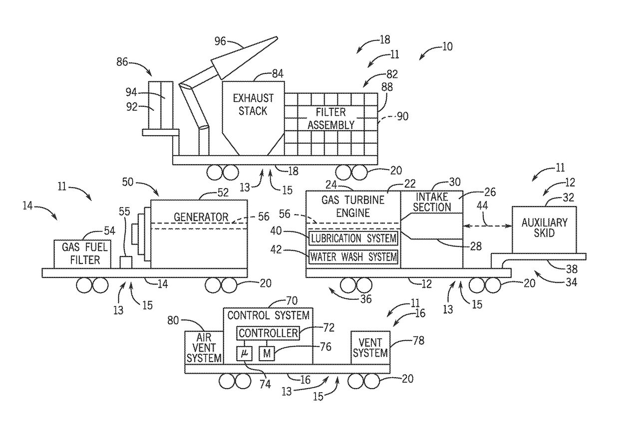
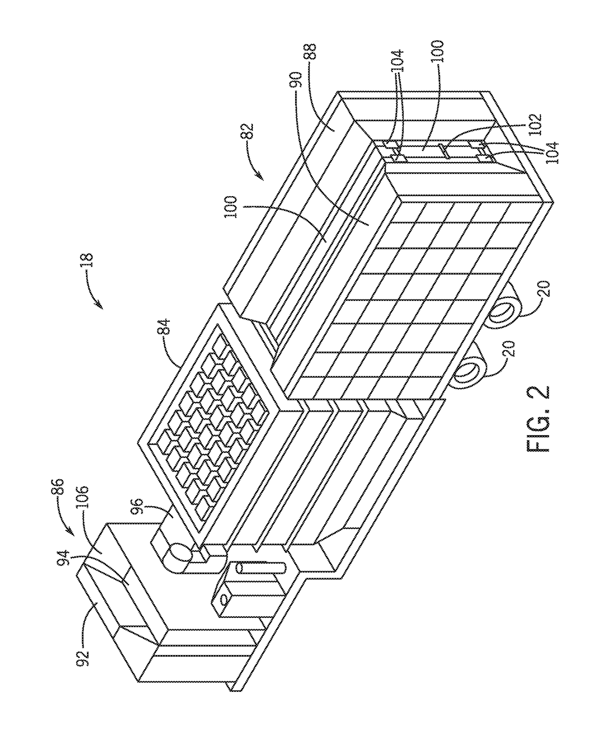
[0058]Technical effects of the invention include transporting components of a mobile power plant system 10 to an installation site via a trailer-mounted system to meet power demands of customers where permanent power plants may not be able to deliver power. In certain embodiments, during the transportation phase of the mobile power plant system 10, the generator trailer 14 may transport the generator 52 that generates power for the mobile power plant system 10. The turbine trailer 12 may transport the gas turbine engine 22, the intake section 30 that includes the silencer 200 disposed within the silencer housing 202, and / or the auxiliary skid 32. In certain embodiments, the auxiliary skid 32 may be disposed at the rear of the turbine trailer 12 and may include a number of components that are coupled (e.g., communicatively coupled) to a number of the components associated with the gas turbine engine 22. Further, during the transportation phase, the control house trailer 16 may transport the control system 70 having the controller 72, the ventilation system 78 for the gas turbine engine 22, and the air ventilation system 80 for the generator 52. Further, in certain embodiments, the transport trailer 18 may transport the filter assembly 82, the air inlet filter assembly 86, and / or the exhaust stack 84.

Problems solved by technology

However, there are a variety of reasons that the permanent power plant may not be able to meet the power demand of the customers.
As further example, natural disasters such as hurricanes and earthquakes can disrupt power for a portion of the customers.
Mobile power plants may be transported to an environment to meet power demands of customers where permanent power plants may not be able to deliver power, or may not be able to deliver power efficiently.

Method used


Image

  • Systems and methods for a mobile power plant with improved mobility and reduced trailer count
  • Systems and methods for a mobile power plant with improved mobility and reduced trailer count
  • Systems and methods for a mobile power plant with improved mobility and reduced trailer count

Examples


Embodiment Construction

[0017]One or more specific embodiments of the present invention will be described below. In an effort to provide a concise description of these embodiments, all features of an actual implementation may not be described in the specification. It should be appreciated that in the development of any such actual implementation, as in any engineering or design project, numerous implementation-specific decisions must be made to achieve the developers' specific goals, such as compliance with system-related and business-related constraints, which may vary from one implementation to another. Moreover, it should be appreciated that such a development effort might be complex and time consuming, but would nevertheless be a routine undertaking of design, fabrication, and manufacture for those of ordinary skill having the benefit of this disclosure.

[0018]When introducing elements of various embodiments of the present invention, the articles “a,”“an,”“the,” and “said” are intended to mean that ther...


PUM


Abstract

A system a first mobile body configured to support a turbine engine and an auxiliary skid communicatively and fluidly coupled to the turbine engine. The auxiliary skid includes one or more interconnects configured to support a turbine engine component. The system also includes a second mobile body configured to support a generator. The first and second mobile bodies are configured to align a removable coupling between the turbine engine and the generator.

Description

BACKGROUND OF THE INVENTION[0001]The subject matter disclosed herein relates to gas turbine systems, and more particularly to systems and methods for transporting and installing mobile turbomachinery.[0002]Typically, permanent power plants are built to provide power to customers connected to a power grid. However, there are a variety of reasons that the permanent power plant may not be able to meet the power demand of the customers. For example, in periods of intense growth, the demand by customers may increase to surpass the amount of power the permanent power plant can generate. In some cases, the permanent plant may be shut down or undergo equipment maintenance. As further example, natural disasters such as hurricanes and earthquakes can disrupt power for a portion of the customers.[0003]Mobile power plants may be transported to an environment to meet power demands of customers where permanent power plants may not be able to deliver power, or may not be able to deliver power effi...

Claims


Application Information

Patent Timeline
Patent Type & Authority Patents(United States)
IPC IPC(8): F02B63/04H02K7/18F03G7/08F02C6/00F02C3/04B60D1/00B62D53/00F16M5/00F16M3/00E21B4/04F02C7/20
CPCF02C6/00B60D1/00B62D53/00F02B63/044F16M3/00F16M5/00H02K7/1823F02C3/04F05D2220/76B60P3/00
Inventor AUSTIN, KENNETH ROBERTSETHI, VINEETFONG, RAYMOND KALOKGUILLEN, JOSE EMMANUELBATEN, ROBERT ALLENLAING, DONALD GORDON
Owner GE INFRASTRUCTURE TECH INT LLC
Learn More