
High efficiency hollow cathode and cathode system applying same

a hollow cathode and high efficiency technology, applied in the direction of discharge tube main electrodes, machine/engines, transit-tube cathodes, etc., can solve the problems of reducing the life of the cathode, affecting the efficiency of the cathode, and inevitably exposed to the atmosphere of the industrial cathode line, so as to improve the life and efficiency, increase the efficiency, and improve the efficiency.

Active Publication Date: 2018-07-24
KOREA ADVANCED INST OF SCI & TECH
View PDF21 Cites 0 Cited by
  • Summary
  • Abstract
  • Description
  • Claims
  • Application Information

AI Technical Summary

Benefits of technology

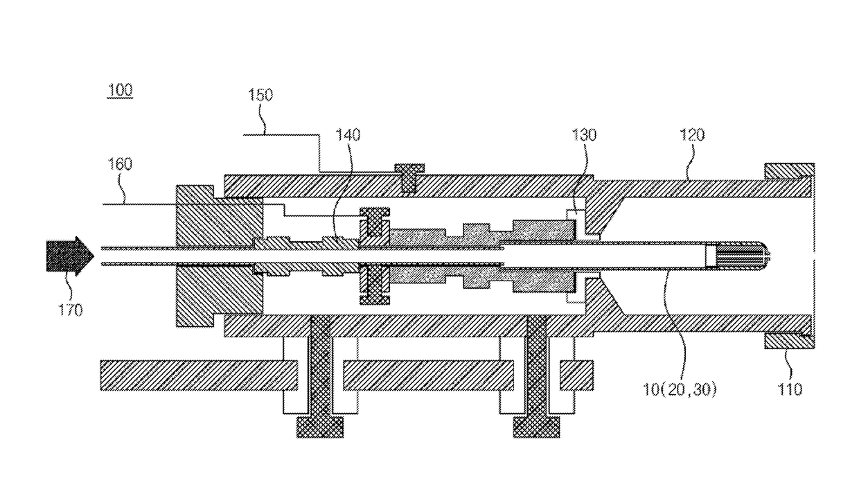
The present invention relates to a high efficiency hollow cathode and a cathode system applying the same. The invention enhances the thermal / electric stability, lifespan, and efficiency of the conventional industrial hollow cathode. The invention uses a refractory metal material as a thermal radiation shielding layer to reduce heat loss and power required and enhance thermal stability. However, the invention also addresses the issue of low work function materials, such as tantalum, losing their effectiveness due to exposure to the atmosphere. The invention proposes a solution to this issue by using a refractory metal material stable to exposure to the atmosphere. Overall, the invention improves the performance and reliability of hollow cathodes for industrial use.

Problems solved by technology

Meanwhile, industrial equipment require maintenance at predetermined intervals, and accordingly, the industrial cathode line is inevitably exposed to the atmosphere (in particular, water and oxygen) repetitively.
The performance of substances having low work function (for example, LaB6) is greatly deteriorated because the work function increases due to change in physical properties by exposure to the atmosphere.
However, when applied for industrial use, continuously exposed to the atmosphere, its lifespan drops sharply (to 1,000 hours or below).
For the hollow cathode using LaB6 (work function: 3 eV or below) which has a representatively low work function as an insert, there is a possibility that the insert may be thermally damaged by the sharp temperature rise.
However, although the conventional art partly reduces heat loss using a thermal radiation shielding layer, it has a structure that does not sufficiently reduce the heat loss by thermal conduction.
This is because a tube of a single material is used, and this has a limitation in reducing heat loss by thermal conduction in terms of production possibility and thermal stability.
However, it cannot be used due to its low melting point (1,941 K).
Thus, although it is effective in being applied as a tube and insert of the cathode, due to the extremely expensive cost of the material, it has low competitiveness in the product market when applied to industrial cathodes.
Thus, although the conventional industrial hollow cathode uses tantalum the most based on its physical properties and cost, there is an unnecessary presumption that the cathode should be made of a single material which limits the optimization of the cathode.
This is because of the physical damage caused by continuous ion bombardment with the insert.
In particular, thin foil is easily damaged by ion bombardment, deteriorating thermal radiation shielding efficiency.
Thus, there are problems in electric stability, etc. such that plasma is discharged in the outside.
Also, since the power applying high potential difference (starter power supply) is only used for initial discharge, it is not economic in terms of its usage.
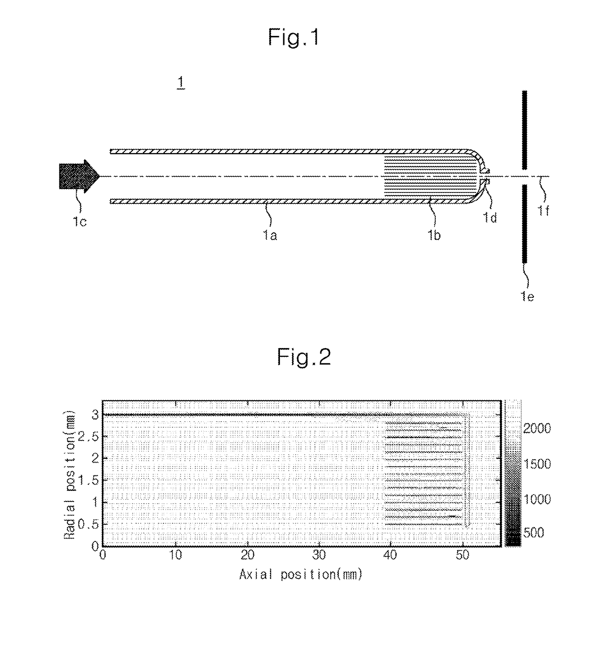
The inner insert 1b-1 constituting the innermost surface of the insert 1b is directly exposed to ion bombardment generated by plasma discharge, and thus may be damaged.
Due to the damage, the effective surface area discharging thermal electrons is reduced and performance deteriorates.
That is, the conventional technology adopts the form of a thin foil (for example, a thickness of 0.013 mm), and thus may be easily damaged by ion bombardment.
Also, as for the conventional insert 1b, since the thin foil layer 1b-2 of the outer part is exposed to ion bombardment due to the damaged inner insert 1b-1 and thus the performance of the thermal radiation shielding layer deteriorates, the calorie required to maintain temperature increases, and thus the performance of the cathode deteriorates.

Method used


Image

  • High efficiency hollow cathode and cathode system applying same
  • High efficiency hollow cathode and cathode system applying same
  • High efficiency hollow cathode and cathode system applying same

Examples


Embodiment Construction

Technical Task

[0042]The present invention was derived in order to solve the above problems. It is an object of the present invention to enhance performance and achieve the effect of saving cost by forming the cathode using at least two substances.

[0043]Also, it is an object of the present invention to enhance the performance by being formed of a thin wire winding the insert that is inserted into the inside of the tube in the form of solenoid.

[0044]Also, it is an object of the present invention to increase electric stability by having the hollow cathode formed of a structure of a thermal insulation connector (cryogenic break) with the gas providing line inside the body.

[0045]Also, it is an object of the present invention to increase economic feasibility by using a cheap low power source and electric condenser instead of a high voltage, high power (starter power supply) used for initial discharge.

Means for Solving the Task

[0046]In order to achieve the above objects, the hollow cathode...


PUM


Abstract

The present invention relates to a high efficiency hollow cathode and a cathode system applying the same, and comprises: a tube comprising at least two refractory metal parts; a gas providing unit and a gas outlet which are respectively formed at the distal ends of the tube; and an insert mounted inside the tube. According to the present invention, since the present invention constitutes a hollow cathode using more than two substances, the present invention can not only enhance thermal stability, lifespan and efficiency, but also can reduce costs accordingly.

Description

CROSS-REFERENCE TO RELATED APPLICATIONS[0001]This application is the United States national phase of International Application No. PCT / KR2015 / 001685 filed Feb. 23, 2015, and claims priority to Korean Patent Application No. 10-2014-0023495 filed Feb. 27, 2014, the disclosures of which are hereby incorporated in their entirety by reference.TECHNICAL FIELD[0002]The present invention relates to a high efficiency hollow cathode and a cathode system applying the same. More specifically, it relates to a high efficiency hollow cathode and a cathode system applying the same, enhancing thermal / electric stability, lifespan and efficiency of the conventional industrial hollow cathode.BACKGROUND ART[0003]A hollow cathode is an electron beam source which discharges a relatively large amount of thermal electrons through plasma discharge and has a long lifespan.[0004]The conventional industrial hollow cathode, externally, has a tube shape made of a refractory metal, and has an insert (in general, t...

Claims


Application Information

Patent Timeline
Patent Type & Authority Patents(United States)
IPC IPC(8): H01J37/32H01J1/02B64G1/40
CPCH01J1/025H01J37/32596B64G1/405F03H1/0031F03H1/0068F03H1/00H01J23/02H01J23/04
Inventor CHOE, WONHOLIM, YOUBONGKIM, HOLAKPARK, JOOYOUNGSEON, JONGHO
Owner KOREA ADVANCED INST OF SCI & TECH
Learn More