High efficiency solid fuel burning stove with optimized burning conditions and low level of emission

Active Publication Date: 2018-08-07
UNIV OF MARYLAND
View PDF1 Cites 3 Cited by
  • Summary
  • Abstract
  • Description
  • Claims
  • Application Information

AI Technical Summary

Benefits of technology

The present system is a solid fuel burning stove that has a forced air inlet that is controlled to optimize fuel-air balance and adjust the force of air for different modes of operation. It also minimizes emissions and provides high efficiency and controlled burning conditions. The stove has air injection manifolds to improve control of the airflow and support fuel-air balance. Overall, the system provides an improved and efficient wood burning stove with controlled and optimized airflow.

Problems solved by technology

However, conventional wood stoves suffer from a number of inadequacies that limit their performance.
Specifically, conventional wood stoves rely exclusively on fire to drive a flow of combustion air, thus limiting the initial airflow and the ability to dynamically and actively regulate a fuel-air balance in the system, which results in a less than optimal burning environment.
The reliance on fire to drive the exhaust also limits the efficiency of the conventional wood stoves since a sufficiently hot exhaust is required to maintain the airflow.
Due to less than optimal burning environment conditions in the conventional wood stoves, large amounts of particulate emissions are produced.
This is a highly undesirable outcome of the conventional stoves operation leading to a lower air quality in areas surrounding wood stoves in use, thus possibly causing health problems.
Fire driven air flow in the conventional wood burning stoves may also create usability issues due to a low level of airflow available during a start-up stage of the wood stoves operation.
A problem faced by many of the contemporary stoves is that during the start-up mode of operation, the burning period which typically produces the most emissions, the catalyst must be by-passed entirely since the heat from the stove is not sufficient to drive the airflow through the thin tubes of the catalyst.
The provisions which would allow such by-pass add to the cost associated with the development and fabrication of the stoves to meet these requirements, and necessitate higher emissions during the start-up.

Method used


Image

  • High efficiency solid fuel burning stove with optimized burning conditions and low level of emission
  • High efficiency solid fuel burning stove with optimized burning conditions and low level of emission
  • High efficiency solid fuel burning stove with optimized burning conditions and low level of emission

Examples


Embodiment Construction

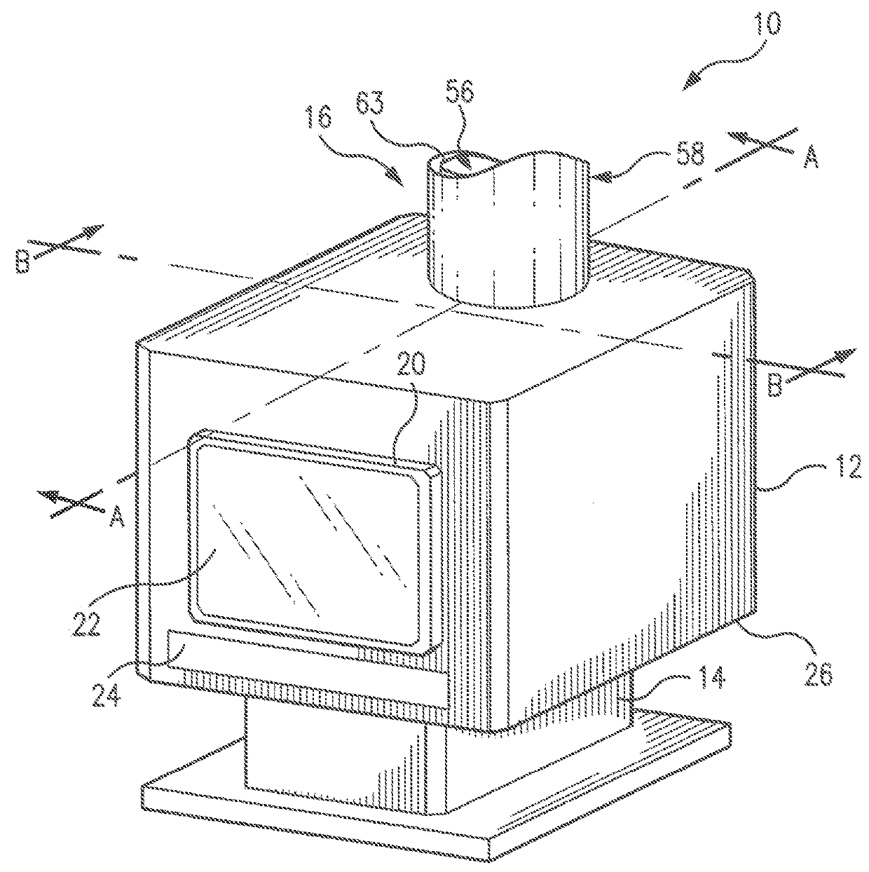
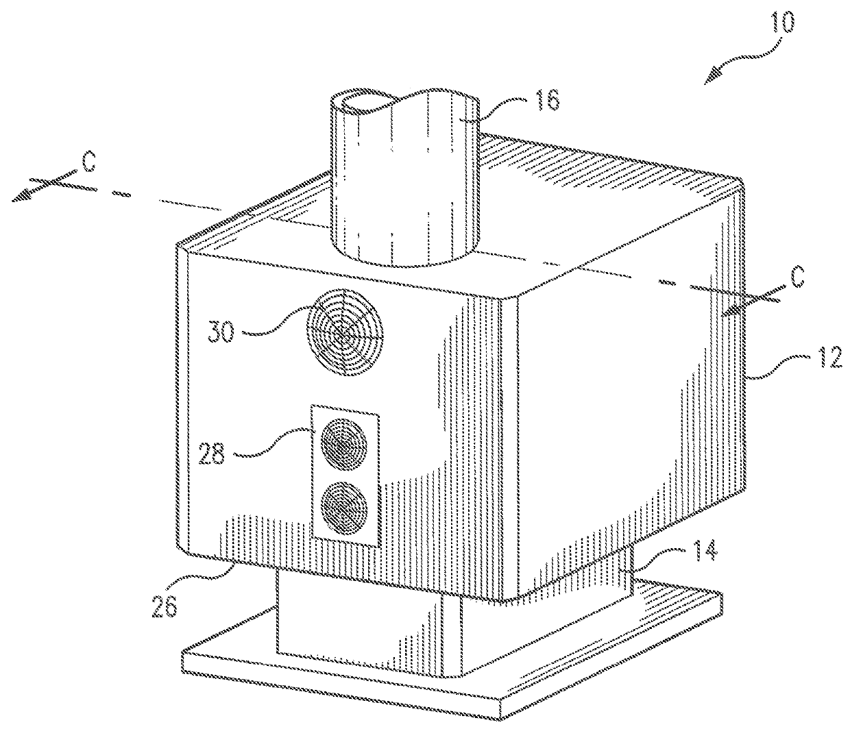
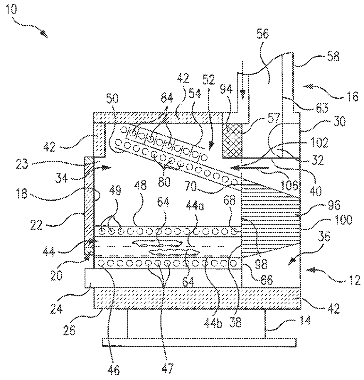
[0083]Referring to FIGS. 1-2, 3A-3B, 4A-4B, and 5-6, the subject stove system 10 includes a main body 12 supported by a stand 14 and ventilated to the exterior through a co-axial stack heat recovery member 16. The stove system 10 may be used for burning solid fuels, such as, for example, coal, wood pellets, corn, etc. However, for the purpose of example, but not for limiting the scope of protection of the present invention, further description will be related to the subject stove as a wood burning stove.

[0084]Although shown as of a somewhat rectangular configuration, the main body 12 of the subject stove 10 may have any other shape appropriate for the function intended. The main body 12 may be fabricated from steel or any other sufficiently strong and heat resistant material.

[0085]The stand 14 which is a supporting member for the main body 12 may be formed in any shape other than that shown, as an example, in FIGS. 1-6, as long as it provides the functions intended and is ergonomica...


PUM


Abstract

A solid fuel stove uses a dynamically controlled Combustion Fan and a Smart Controller system for automatic regulation of combustion conditions through the controlled forced air circulation based on sensors readings. The stove also uses emission reducing and efficiency boosting equipment such as a co-axial stack heat recovery sub-system and a self-cleaning particulate collector with enhanced particulates trapping capabilities.

Description

REFERENCE TO THE RELATED PATENT APPLICATIONS[0001]This Utility Patent Application is based on the Provisional Patent Application No. 61 / 905,025 filed 15 Nov. 2013.FIELD OF THE INVENTION[0002]The present system relates to heat sources, and in particular to solid fuel burning stoves demonstrating high burning efficiency, extremely low levels of emission, which is particularly applicable for heating residential and office buildings.[0003]More in particular, the present system is directed to solid fuel burning stoves in which improved performance characteristics and high burning efficiency are attained through forced air ventilation and dynamical control of a multi-phase burning process carried out in the stove facilitated by the use of a smart controller configured to support an optimal forced air distribution through the system.[0004]The present system is further directed to a wood burning stove system promoting user friendliness, and producing a reduced level of particulates emission...

Claims


Application Information

Patent Timeline
IPC IPC(8): F23N1/00F24B1/02F24B5/02F23J15/02F23L9/00F23L15/02F24B13/02
CPCF24B1/028F24B5/026F24B13/02F23L15/02F23L9/00F23J15/022F23J15/02F23B80/04F23J3/04F23L9/02F23L9/04F23L9/06F24B1/006Y02E20/34
Inventor MYERS, TAYLORFISHER, RYANSTOLIAROV, STANISLAV I
Owner UNIV OF MARYLAND
Why Eureka
Try Eureka