Decompression device

a decompression device and liquid phase technology, applied in mechanical devices, lighting and heating apparatuses, refrigeration components, etc., can solve the problems of not being able to reduce the droplet (a drop of liquid phase refrigerant) and the shock wave generated at the time of the start of the boiling of the refrigerant is not easily attenuated, so as to reduce the noise generation of the decompression device as

Inactive Publication Date: 2018-08-14
DENSO CORP
View PDF37 Cites 1 Cited by
  • Summary
  • Abstract
  • Description
  • Claims
  • Application Information

AI Technical Summary

Benefits of technology

[0008]The disclosure has been made in consideration of the above description, and an object of the invention is to reduce causes of noise generation of a decompression device that is applied to a vapor compression refrigeration cycle.
[0011]Accordingly, since the refrigerant having immediately flowed into the throttle space can be depressurization-boiled, the boiling delay of the refrigerant in the throttle space can be limited. That is, causes of noise generation, which is caused by the occurrence of the boiling delay of the refrigerant, can be reduced. Further, since the refrigerant, which has flowed into the throttle space, can be made to stably start to be boiled in the vicinity of the smallest passage area portion, the variation of the flow rate of the refrigerant flowing out of the decompression device can also be limited.
[0013]Therefore, the causes of noise generation of the decompression device as a whole can be reduced by the reduction of both the cause of noise generation that is caused by the boiling delay of the refrigerant that has flowed into the throttle space and the cause of noise generation that is caused by a shock wave generated due to depressurization.

Problems solved by technology

For this reason, there is a concern that boiling delay of the refrigerant that has flowed into the throttle passage may occur.
When boiling delay occurs, the size of a droplet (a drop of liquid phase refrigerant) is not reduced and a shock wave generated at the time of the start of the boiling of the refrigerant is not easily attenuated.
For this reason, a refrigerant may cause noise to be generated in a refrigeration cycle.
For this reason, there is a concern that noise may also be generated due to a collision between a droplet and the wall surface of the refrigerant passage.

Method used


Image

  • Decompression device
  • Decompression device
  • Decompression device

Examples


first embodiment

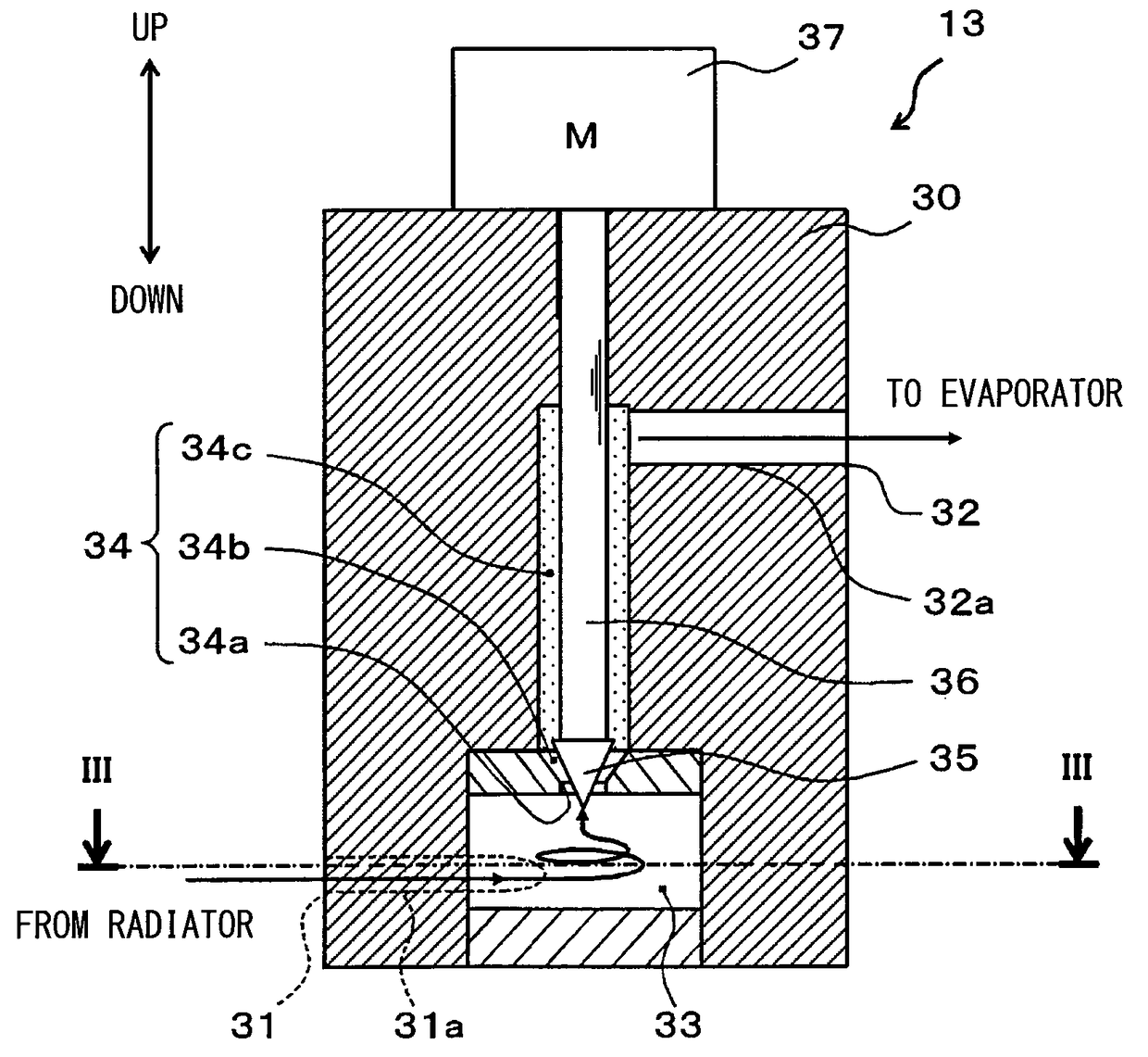
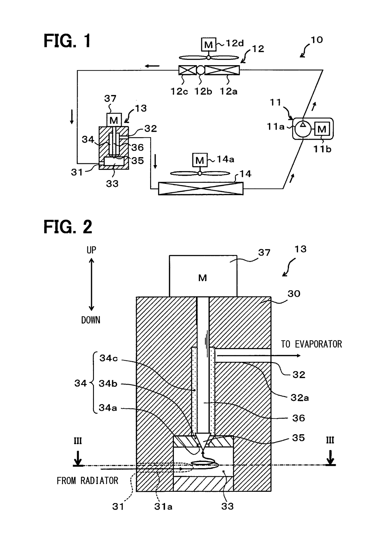
[0030]A first embodiment of the present disclosure will be described with reference to FIGS. 1 to 3. A decompression device 13 of this embodiment is applied to a vapor compression refrigeration cycle 10 as shown in FIG. 1. Moreover, the refrigeration cycle 10 is applied to a vehicle air conditioning system, and cools air blown into a vehicle interior that is an air-conditioning target space.

[0031]First, in the refrigeration cycle 10, a compressor 11 sucks a refrigerant, raises pressure until the refrigerant becomes a high-pressure refrigerant, and discharges the refrigerant. Specifically, the compressor 11 of this embodiment is an electric compressor in which a fixed-capacity compression mechanism 11a and an electric motor 11b for driving the compression mechanism 11a are accommodated in a single housing.

[0032]Various compression mechanisms, such as a scroll-type compression mechanism and a vane-type compression mechanism, can be employed as the compression mechanism 11a. Further, t...

second embodiment

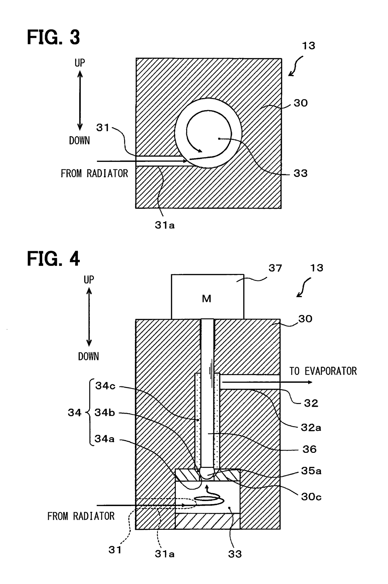
[0069]An example in which the valve body 35 formed in a conical shape is employed as a valve body of the decompression device 13 has been described in the first embodiment, but a valve body 35a formed in a spherical shape as shown in FIG. 4 is employed in this embodiment. Meanwhile, the same portions as the portions of the first embodiment or portions equivalent to the portions of the first embodiment are denoted by the same reference numerals in FIG. 4. This is also the same in the following drawings.

[0070]Further, a cylindrical space (straight portion) and a circular truncated conical space (tapered portion), which continues from the cylindrical space and is increased in diameter in a refrigerant flow direction, are formed in a passage formation member 30c that forms the most upstream portion of a refrigerant passage space 34 disposed on the outer peripheral side of the valve body 35a. Further, in this embodiment, the smallest passage area portion 34a is formed at a connection por...

third embodiment

[0073]The decompression device 13, which electrically displaces the actuating bar 36 and the valve body 35 by the electric actuator 37, has been described in the first embodiment, but an example in which the actuating bar 36 and a valve body 35c are mechanically displaced by a diaphragm 38b as a pressure responsive member will be described in this embodiment. More specifically, a decompression device 13 of this embodiment is formed of a so-called uniform internal pressure-temperature type expansion valve as shown in a cross-sectional view of FIG. 6.

[0074]First, a second refrigerant inflow passage 31b through which a low-pressure refrigerant that has flowed out of the evaporator 14 flows into the body part, and a second refrigerant outflow passage 32b through which a refrigerant that has flowed out of the second refrigerant inflow passage 31b and flowing out of the evaporator 14 flows into the suction side of the compressor 11 are formed in a body part 30 of this embodiment in additi...


PUM


Abstract

A body part of a decompression device is provided with a swirling space that allows a refrigerant from a refrigerant inlet to swirl, a throttle space that depressurizes the refrigerant that has flowed out of the swirling space, and a downstream-side space that is disposed on the downstream side of the throttle space in a refrigerant flow and is formed so that the pressure of a refrigerant present in the downstream-side space becomes uniform.

Description

CROSS REFERENCE TO RELATED APPLICATIONS[0001]This application is a U.S. National Phase Application under 35 U.S.C. 371 of International Application No. PCT / JP2013 / 003218 filed on May 21, 2013 and published in Japanese as WO 2013 / 190768 A1 on Dec. 27, 2013. This application is based on and claims the benefit of priority from Japanese Patent Application No. 2012-140773 filed on Jun. 22, 2012. The entire disclosures of all of the above applications are incorporated herein by reference.TECHNICAL FIELD[0002]The present disclosure relates to a decompression device that is applied to a vapor compression refrigeration cycle.BACKGROUND ART[0003]In the past, Patent Document 1 disclosed a decompression device in which an ejector is connected to a refrigerant outlet of a temperature type expansion valve, as a decompression device that is applied to a vapor compression refrigeration cycle.[0004]In the decompression device disclosed in Patent Document 1, the pressure recovery of a refrigerant, wh...

Claims


Application Information

Patent Timeline
Patent Type & Authority Patents(United States)
IPC IPC(8): F25B41/06
CPCF25B41/062F25B41/06F25B2341/0653Y02B30/72F25B2500/12F25B2500/13F25B2341/0683F16K1/32F16K47/026F25B41/35F25B41/335Y02B30/70
Inventor AWA, RYOKOYAMADA, ETSUHISANISHIJIMA, HARUYUKITAKANO, YOSHIAKI
Owner DENSO CORP
Why Eureka
Try Eureka