
Systems, methods, and apparatuses for monitoring and/or controlling the density of a fluid

a technology of density meter and fluid, which is applied in the direction of instruments, specific gravity measurement, measurement devices, etc., can solve the problems of brew contamination, need to break the seal,

Inactive Publication Date: 2018-08-14
PARASITX LLC
View PDF15 Cites 1 Cited by
  • Summary
  • Abstract
  • Description
  • Claims
  • Application Information

AI Technical Summary

Benefits of technology

The present invention provides a system and method for real-time monitoring, measuring, and controlling a fluid during fermentation. By using a hydrometer arrangement and accessing an application or display, users can easily determine the current density of a fluid and the direction of the density trend without needing to constantly interact with it. This helps ensure consistency from batch to batch. The invention provides a user-friendly way to visualize and manage the density of a fluid. Additionally, the invention provides a density meter that can be easily operated and used by users. Overall, the invention improves the fermentation process by providing a more efficient and effective means for monitoring and managing the fluid.

Problems solved by technology

One limitation of using a laboratory device to measure the density during fermentation is, as discussed above, the need to break the seal.
Breaking the seal during the fermentation process of beer, wine, or other substance to take a sample and make a hydrometer reading can lead to contamination of the brew.

Method used


Image

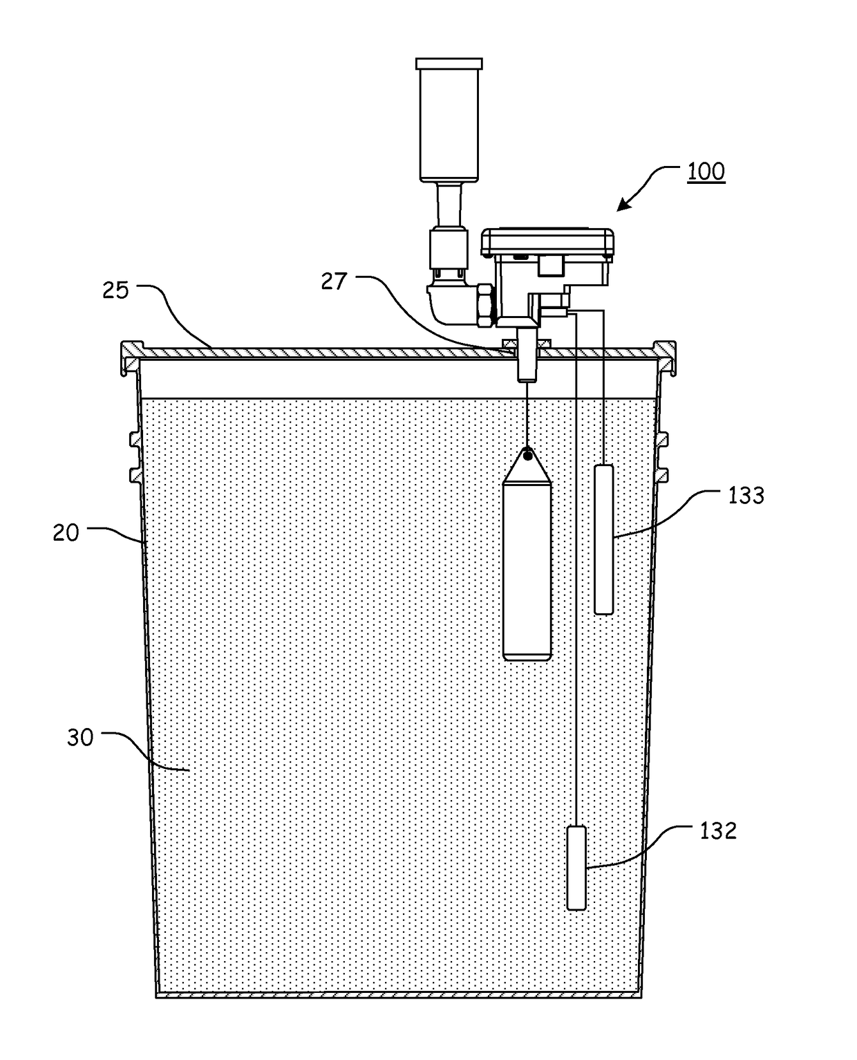
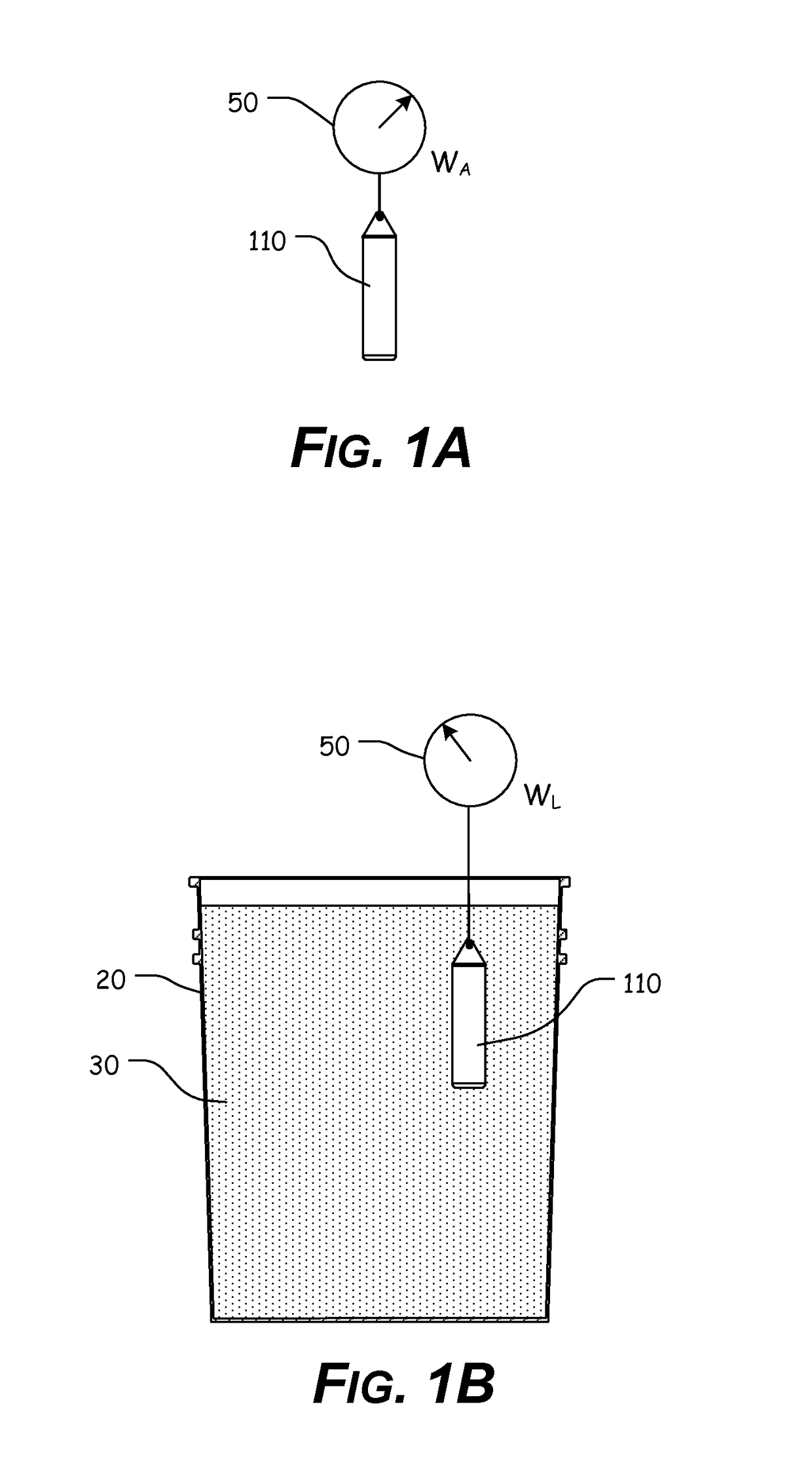
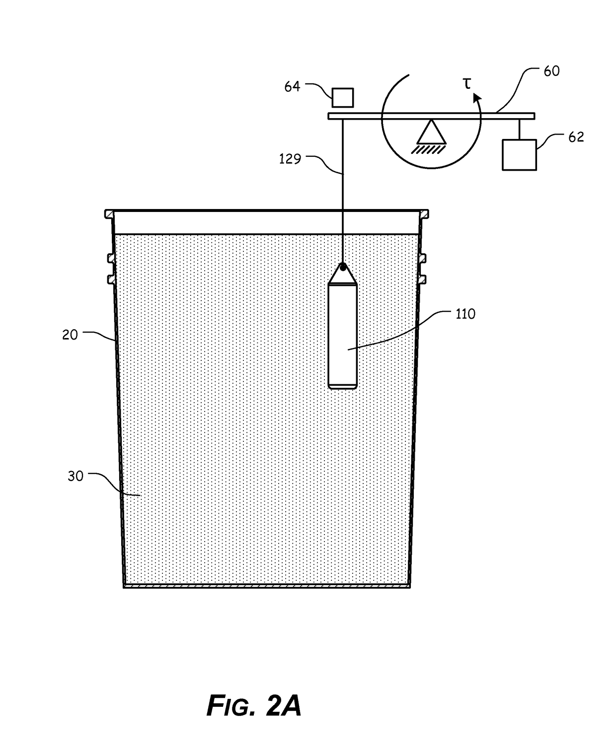
  • Systems, methods, and apparatuses for monitoring and/or controlling the density of a fluid
  • Systems, methods, and apparatuses for monitoring and/or controlling the density of a fluid
  • Systems, methods, and apparatuses for monitoring and/or controlling the density of a fluid

Examples


Embodiment Construction

[0096]For simplicity and clarification, the design factors and operating principles of the density meter according to this invention are explained with reference to various exemplary embodiments of a density meter according to this invention. The basic explanation of the design factors and operating principles of the systems, methods, and apparatuses of the present invention is applicable for the understanding, design, and operation of the systems, methods, and apparatuses of this invention. It should be appreciated that the density meter can be adapted to many applications where a density meter can be used.

[0097]As used herein, the word “may” is meant to convey a permissive sense (i.e., meaning “having the potential to”), rather than a mandatory sense (i.e., meaning “must”). Unless stated otherwise, terms such as “first” and “second” are used to arbitrarily distinguish between the elements such terms describe. Thus, these terms are not necessarily intended to indicate temporal or o...


PUM

PropertyMeasurementUnit
capacitanceaaaaaaaaaa
densityaaaaaaaaaa
densityaaaaaaaaaa

Abstract

A density meter for measuring the density of a fluid, having a base plate, wherein a spring element is clamped to the base plate; a torpedo, wherein the torpedo comprises a known weight, and wherein the torpedo is attached or coupled to the spring element; and a sensor, wherein the sensor measures a deflection of the spring element, as the torpedo displaces a volume of fluid.

Description

CROSS-REFERENCE TO RELATED APPLICATIONS[0001]This patent application claims the benefit of U.S. Patent Application Ser. No. 61 / 961,213, filed Oct. 9, 2013, the entire disclosure of which is incorporated herein by reference.STATEMENT REGARDING FEDERALLY SPONSORED RESEARCH OR DEVELOPMENT[0002]Not Applicable.REFERENCE TO SEQUENCE LISTING, A TABLE, OR A COMPUTER PROGRAM LISTING COMPACT DISC APPENDIX[0003]Not Applicable.NOTICE OF COPYRIGHTED MATERIAL[0004]The disclosure of this patent document contains material that is subject to copyright protection. The copyright owner has no objection to the reproduction by anyone of the patent document or the patent disclosure, as it appears in the Patent and Trademark Office patent file or records, but otherwise reserves all copyright rights whatsoever. Unless otherwise noted, all trademarks and service marks identified herein are owned by the applicant.BACKGROUND OF THE INVENTION[0005]1. Field of the Invention[0006]The present disclosure relates ge...

Claims


Application Information

Patent Timeline
Patent Type & Authority Patents(United States)
IPC IPC(8): G01N9/00G01N9/02G01N9/12G01N9/18G01N9/10
CPCG01N9/002G01N9/10G01N9/02G01N2009/024
Inventor WRIGHT, DAVID D.VOGELEY, JAMES H.MCCLENNY, TAYLOR D.MERRICK, PETER R.ROBINSON, PAUL A.
Owner PARASITX LLC
Learn More