Quantum dots with reduced saturation quenching

a quantum dots and saturation quenching technology, applied in semiconductor devices, lighting and heating apparatus, instruments, etc., can solve the problems of substantially white light produced by defects, and achieve the effect of reducing the radiative lifetime, enhancing the efficiency, and reducing the efficiency of light converters and/or lighting devices

Active Publication Date: 2018-08-14
LUMILEDS
View PDF15 Cites 3 Cited by
  • Summary
  • Abstract
  • Description
  • Claims
  • Application Information

AI Technical Summary

Benefits of technology

[0051]Especially for plasmonic structures it may be desirable to have the quantum dot core at a non-zero distance from the plasmonic elements that constitute the plasmonic structure. Especially, the shortest distance between the core and a plasmonic element, such as a metal (plasmonic) element, may be at least 5 nm, such as at least 10 n. This may for instance be achieved by a coating on the core, such as in the case of a core-shell quantum dot. Bare cores, i.e. bare quantum dots, may also be applied but are thus especially arranged at a shortest distance of at least 5 nm of the plasmonic elements. Such coating or shell may e.g. a silica coating or shell, though the quantum dot may also be part of a larger structure, such as a silica structure. In these ways, the distance between the quantum dot core and the plasmonic elements can be easily tuned. Thereby, also the optimal distance between the core and the elements of the optical structure can be tuned. It further appears that some coatings on the quantum dots may provide further advantageous effects, especially in terms of stability and efficiency. Hence, in an embodiment the quantum dot comprises a silica coating. Other coatings than silica, like alumina, titania, or a combinations of two or more coating, may also be possible. Note that the quantum dots as described herein may also include core-shell quantum dots or QD rods (which may also be of the core-shell type) (see also below). Such coated quantum dots may be included in optical structure. Alternatively, the coating may form part of the optical structure. For instance, one may grow the optical structure around the quantum dot(s) and thereby provide the optical structure and implicitly the coating. Hence, in a further embodiment the optical structure comprises a silica structure.
[0052]In a specific embodiment, the quantum dot has a shortest distance to a metallic structure comprised by the optical structure of at least 5 nm, especially at least 10 nm, even more especially at least 15 nm. Especially in the case of plasmonic structures, metal elements may be used. Hence, in such light converter, especially the quantum dots are arranged at a distance of at least 5 nm, especially at least 10 nm, even more especially at least 15 nm. This appears to (further) enhance the efficiency. Too low distances may provide a non-radiative decay path. Especially, the herein indicated distance refers to the shortest distance, even more especially a number averaged shortest distance. Further, as indicated above the distance is especially the shortest distance between the QD core and the (metal) plasmonic element. As also indicated above, to obtain such minimum distance, e.g. a coating (like a shell) or a structure around the bare QDs may be applied. Alternatively or additionally, giant quantum dots may be applied.
[0053]Hence, in an embodiment the optical structure may comprises one or more of a photonic crystal structure and plasmonic optical structure, wherein said optical structure, such as a plasmonic structure comprises, a silica structure comprising said quantum dots. This may also include a silica structure comprising photonic structure elements (like holes, etc.) and / or plasmonic elements, such as metal structures that may provide the plasmonic optical structure. Especially said quantum dots (more precisely quantum dot cores) have (in such structure) a shortest distance to a metallic structure (or other plasmonic structure) and / or photonic crystal structure element comprised by the optical structure (30) of at least 5 nm.
[0054]In a specific embodiment, the quantum dot(s) has (have) a quantum efficiency of at least 90%, even more especially at least 95%. Even then the efficiency (or efficacy) of the light converter and / or lighting device may be very high with the presently provided solution. The quantum dot(s) may have in the light converter a radiative decay time of 4 ns or less, such as 2 ns or less, or even 1 ns or less. Hence, outside the light converter, or more especially, outside of the optical structures, the radiative decay of the emission may be in the range of at least 10 ns, such as at least 15 ns, like at least 20 ns, such as in the range of 15-50 ns, such as 20-40 ns. However, within the optical structures as described herein, the radiative lifetime may be reduced substantially, such as in the range of ⅕ or less, or even 1 / 10 or less of the original radiative decay time. To the best of our knowledge, there are no examples known of reduction of QD saturation by these photonic or plasmonic structures.
[0055]The invention enables efficient (QD-converted) LED light sources at high flux densities, for example LED lamps, spot lights, outdoor lighting, automotive lighting and / or laser applications.
[0056]The term “quantum dots” or “luminescent quantum dots” may also refer to a combination of different type of quantum dots, i.e. quantum dots that have different spectral properties. The QDs are herein also indicated as “wavelength converter nanoparticles”. The term “quantum dots” especially refer to quantum dots that luminescence in one or more of the UV, visible and IR (upon excitation with suitable radiation, such as UV radiation).

Problems solved by technology

In combination, the defects can produce substantially white light.

Method used


Image

  • Quantum dots with reduced saturation quenching
  • Quantum dots with reduced saturation quenching
  • Quantum dots with reduced saturation quenching

Examples


Embodiment Construction

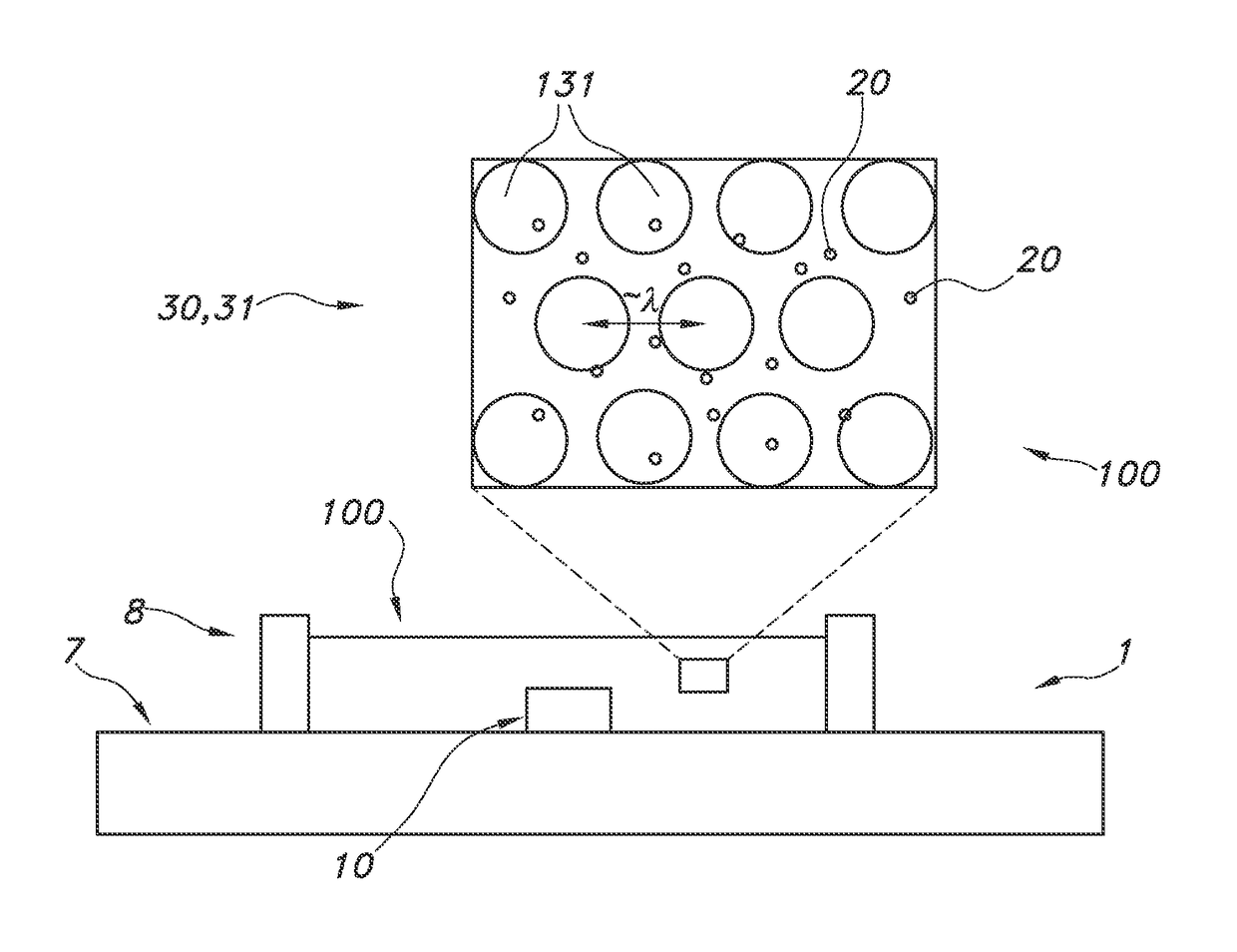
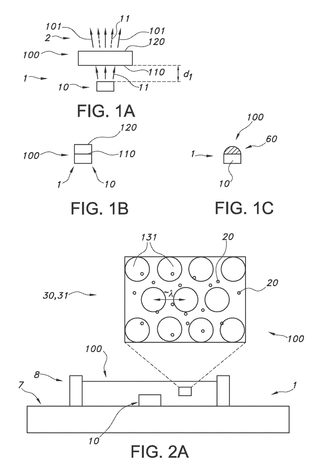
[0098]FIGS. 1a-1c schematically depict some embodiments of the lighting unit. The lighting unit is indicated with reference 1; the light source with reference 10 and the light converter with reference 100. The light source may e.g. a LED with a die (not depicted) from which light source light emanates. The light source light generated by the light source 10 is indicated with reference 11. There may be a non-zero distance between the light converter 100 and the light source. The distance is indicated with reference d1, and may be in the range of 0.1 mm-10 cm. However, this distance may also be zero, as schematically depicted in FIG. 1b.

[0099]The light converter may include a light receiving face 110, which is directed to the light source 10, and a light exit face 120 (in general opposite of the light receiving face 110). From this face light converter light 101 may emanate. However, it is not excluded that this light may also escape from one or more other faces, including the light ...


PUM

PropertyMeasurementUnit
quantum efficiencyaaaaaaaaaa
FWHMaaaaaaaaaa

Abstract

The invention provides a lighting device comprising (a) a light converter comprising a light receiving face; and (b) a solid state light source configured to generate a light source light with a photon flux of at least 10 W / cm2 at the light receiving face, wherein the light converter is configured to convert at least part of the light source light into light converter light having a first frequency, wherein the light converter comprises a semiconductor quantum dot in an optical structure selected from a photonic crystal structure and a plasmonic structure, wherein the optical structure is configured to increase the photon density of states in the light converter resonant with the first frequency for reducing saturation quenching, and wherein the quantum dot has a quantum efficiency of at least 80%.

Description

CROSS-REFERENCE TO RELATED APPLICATIONS[0001]The present application is a § 371 application of International Application No. PCT / EP2015 / 057536 filed on Apr. 8, 2015 and entitled “QUANTUM DOTS WITH REDUCED SATURATION QUENCHING,” which claims priority to European Patent Application No. 14165934.2, filed Apr. 25, 2014. Applications PCT / EP2015 / 057536 and EP14165934.2 are incorporated herein.FIELD OF THE INVENTION[0002]The invention relates to a lighting device comprising a light converter, wherein the light converter comprises semiconductor quantum dots. The invention further relates to such light converter.BACKGROUND OF THE INVENTION[0003]The application of quantum dots for lighting is known in the art. US2008315177, for instance, describes devices and methods for emitting substantially white light using a photonic crystals. The photonic crystal has a lattice of air holes and is made from a substrate containing quantum dots. The substrate is etched with three defects that are optically...

Claims


Application Information

Patent Timeline
Patent Type & Authority Patents(United States)
IPC IPC(8): G02F1/35H01L33/50G02F2/02
CPCH01L33/502H01L33/507H01L2933/0083B82Y20/00G02B6/1226F21K9/20G02B6/1225H01L33/04H01L33/50F21Y2115/10
Inventor KOOLE, ROELOFLUNZ, MANUELAVELDMAN, DIRKBAESJOU, PATRICK JOHN
Owner LUMILEDS
Why Eureka
Try Eureka