Latching arrangement for switchable rocker arm

a technology of latching arrangement and rocker arm, which is applied in the direction of mechanical equipment, machines/engines, engine components, etc., can solve the problems of frequent tooling breakage and difficulty in forming oil supply bores, and achieve the effect of easing manufacturing and reducing costs

Active Publication Date: 2018-08-21
DELPHI TECH IP LTD
View PDF4 Cites 3 Cited by
  • Summary
  • Abstract
  • Description
  • Claims
  • Application Information

AI Technical Summary

Benefits of technology

[0006]Briefly described, a rocker arm is provided for transmitting rotational motion from a camshaft to opening and closing motion of a combustion valve in an internal combustion engine. The rocker arm includes an outer arm with an outer follower; an inner arm which selectively pivots relative to the outer arm, the inner arm having an inner follower; and a latching arrangement which switches the rocker arm between a coupled state and a decoupled state. The latching arrangement includes a connecting bore which extends into the outer arm, the connecting bore being centered about and extending along a connecting bore axis such that the connecting bore is terminated by a connecting bore floor; an oil supply bore in the outer arm which opens into the connecting bore through the connecting bore floor, the oil supply bore being centered about and extending along an oil supply bore axis; a lock pin bore in the outer

Problems solved by technology

As a result of the inclined nature of the oil supply bore breaking into the lock pin bore, it is not practical to initiate the hole from the lock pin bore, and consequently, formation of the oil supply bore is initiate

Method used


Image

  • Latching arrangement for switchable rocker arm
  • Latching arrangement for switchable rocker arm
  • Latching arrangement for switchable rocker arm

Examples


Embodiment Construction

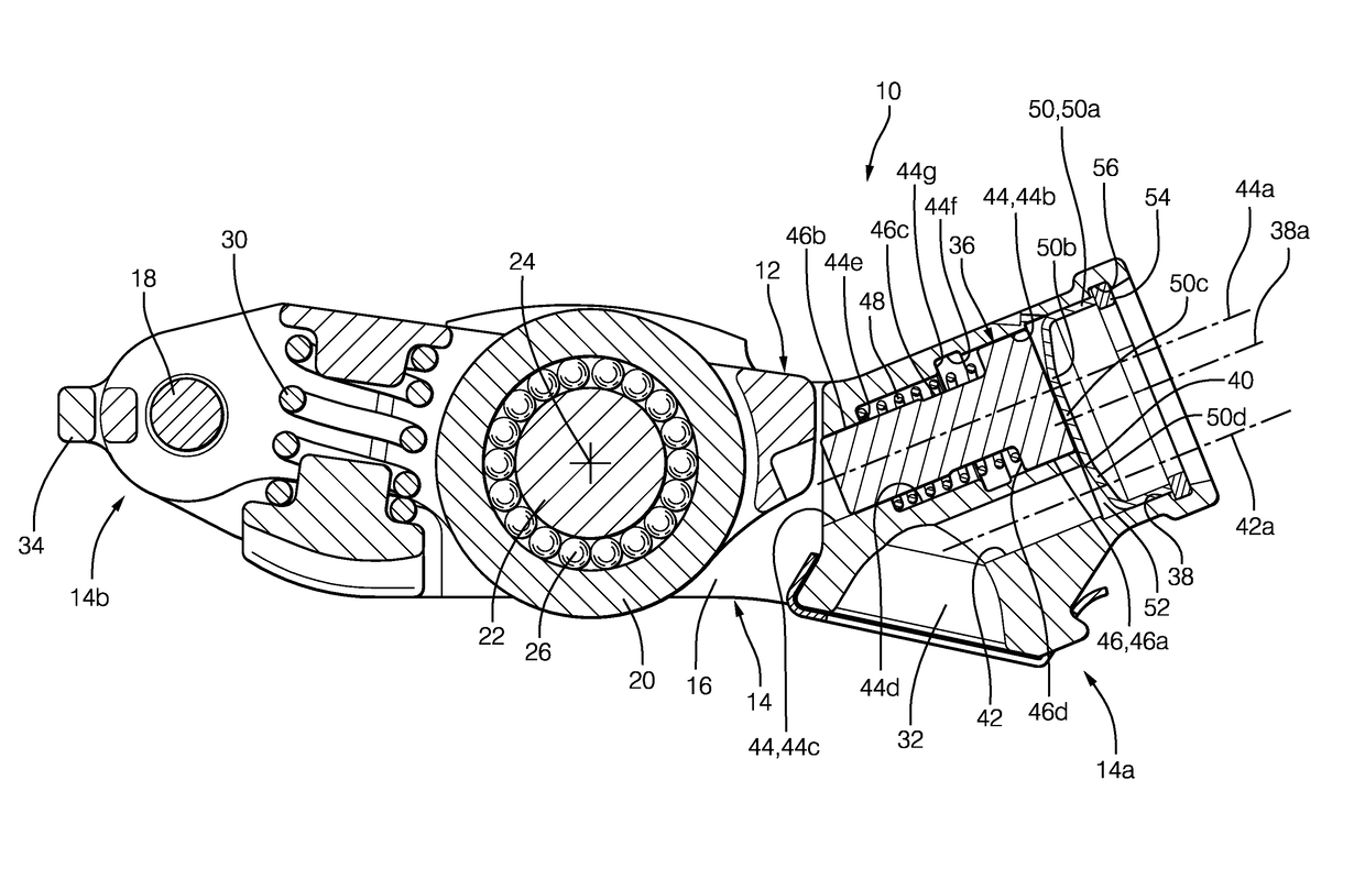
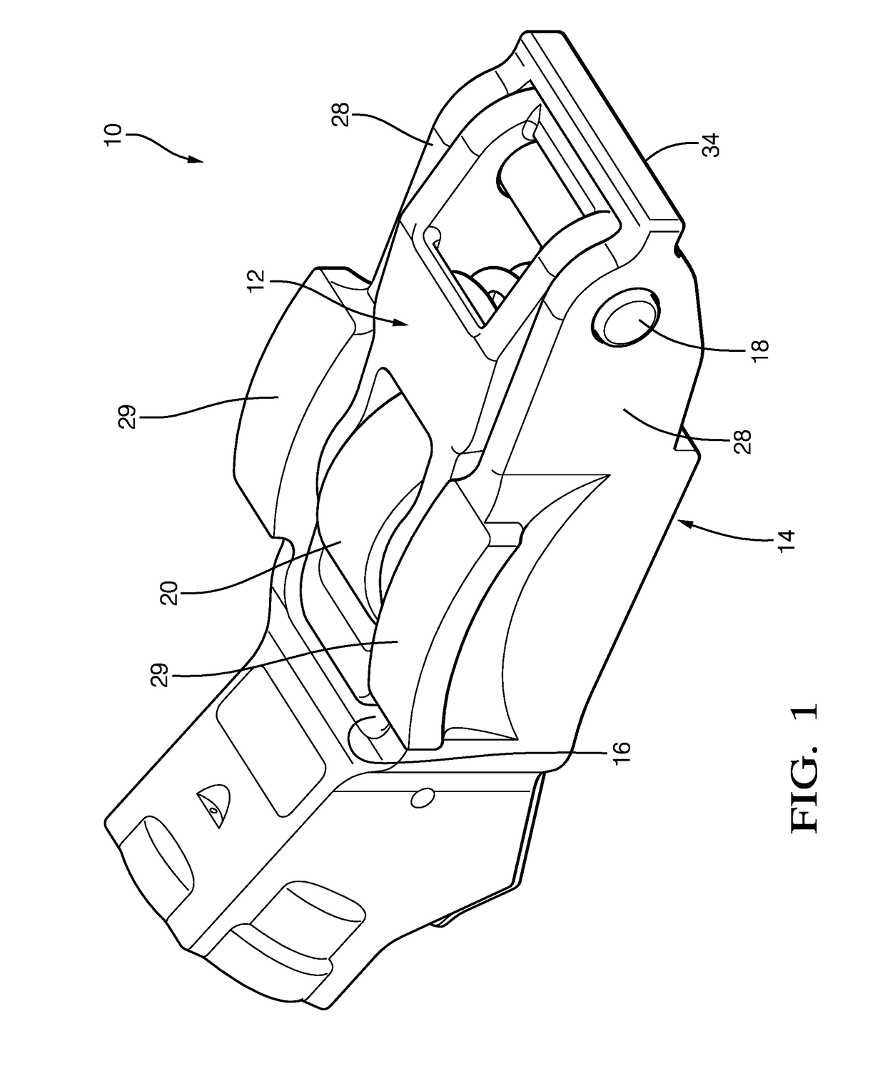
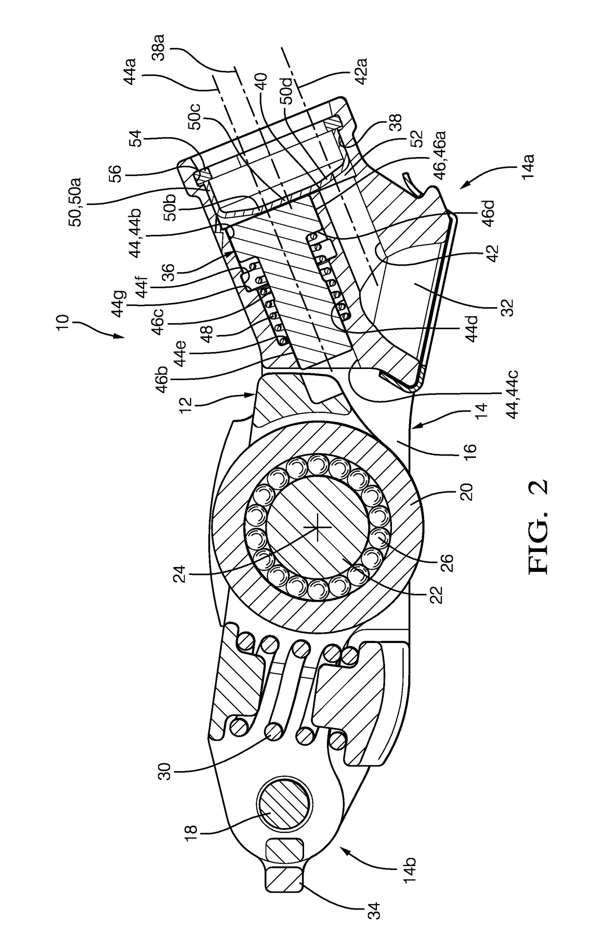
[0012]Referring to FIGS. 1-4, a rocker arm 10 in accordance with the invention is illustrated where rocker arm 10 is either a two-step rocker arm or a deactivation rocker arm, which may generically be referred to as a switchable rocker arm. Rocker arm 10 is included in valve train (not shown) of an internal combustion engine (not shown) in order to translate rotational motion of a camshaft (not shown) to reciprocating motion of a combustion valve (not shown). Rocker arm 10 includes an inner arm 12 that is pivotably disposed in a central opening 16 in an outer arm 14. Inner arm 12 selectively pivots within outer arm 14 about a pivot shaft 18. Inner arm 12 includes a follower illustrated as a roller 20 carried by a roller shaft 22 that is supported by inner arm 12 such that roller 20 and roller shaft 22 are centered about a roller shaft axis 24. Roller 20 is configured to follow a lobe of the camshaft, for example a high-lift lobe, to impart lifting motion on a respective combustion v...


PUM


Abstract

A rocker arm includes an outer arm; an inner arm which selectively pivots relative to the outer arm; and a latching arrangement which switches the rocker arm between a coupled state and a decoupled state. The latching arrangement includes a connecting bore which is terminated by a connecting bore floor; an oil supply bore which opens into the connecting bore through the connecting bore floor; a lock pin bore which opens into the connecting bore through the connecting bore floor; a lock pin within the lock pin bore where the lock pin prevents the inner arm from pivoting in the coupled state and where the lock pin permits the inner arm to pivot in the coupled state; and a retainer within the connecting bore which defines a chamber within the connecting bore which provides fluid communication between the oil supply bore and the lock pin bore.

Description

TECHNICAL FIELD OF INVENTION[0001]The present invention relates to a rocker arm for valve train of an internal combustion engine; more particularly to a rocker arm with an inner arm which selectively pivots relative to an outer arm, and even more particularly to a latching arrangement which selectively couples the inner arm to the outer arm and which selectively decouples the inner arm from the outer arm.BACKGROUND OF INVENTION[0002]Variable valve activation mechanisms for internal combustion engines are well known. It is known to lower the lift, or even to provide no lift at all, of one or more valves of an internal combustion engine, during periods of light engine load. Such valve deactivation or valve lift switching can substantially improve fuel efficiency.[0003]A rocker arm acts between a rotating eccentric camshaft lobe and a pivot point on the internal combustion engine, such as a hydraulic lash adjuster, to open and close an engine valve. Switchable rocker arms may be a “dea...

Claims


Application Information

Patent Timeline
IPC IPC(8): F01L1/18F01L1/24F01L1/047
CPCF01L1/181F01L1/047F01L1/2416F01L2001/186F01L1/185F01L13/0005F01L13/0036F01L2001/467
Inventor WEST, JOSEPH M.JERMY, IAN R.
Owner DELPHI TECH IP LTD
Why Eureka
Try Eureka