
Adaptive high integrity ESD system

a high integrity, esd technology, applied in the direction of process and machine control, testing/monitoring control system, instruments, etc., can solve the problems of no partial-stroke device that can interchangeably support both types of actuators, current partial-stroke devices, and inability to meet the needs of the customer, so as to improve the detection of valve performance and readiness, reduce the probability of failure, and facilitate integration

Active Publication Date: 2018-08-28
SAUDI ARABIAN OIL CO
View PDF11 Cites 0 Cited by
  • Summary
  • Abstract
  • Description
  • Claims
  • Application Information

AI Technical Summary

Benefits of technology

[0012]The invention allows for better detection of valve performance and readiness, and reduces the probability of failures on demand over prior art systems employing partial stroke methods. The invention can be easily integrated into existing emergency shutdown systems, and the capital cost will eventually be paid for by cost savings from the elimination of the man hours associated with prior art partial stroke testing methods.

Problems solved by technology

However, a full stroke of the valve interrupts process flow, which is frequently impractical and economically undesirable.
As a consequence of the effect of a partial stroke test on process variables, and as a consequence of the manpower costs associated with partial stroke tests, they are typically only performed every 3-12 months.
There are a number of other disadvantages associated with the current partial-stroke devices.
Some models can operate with a pneumatic actuator, and other models can operate with a hydraulic actuator, but there is no partial-stroke device that can interchangeably support both types of actuators.
Actuator quick exhausts cannot be tested with the current partial-stroke devices.
Another disadvantage is that the precise amount of closure (i.e., within the typical 10-30% closure range) is generally established for a particular valve based upon operating points and process variables that occur during a test.
When the valve is repeatedly tested with a partial stroke to the same percentage of closure, this increases the possibility of creating a crest or ridge on the valve obturator.
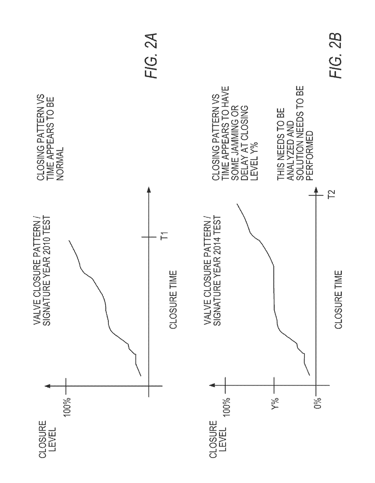
Once a ridge on the valve obturator develops, all subsequent partial stroke tests may indicate the valve is functioning properly, while in reality, an actual closure demand may fail due to the valve obturator jamming on the seat, locking the ESD valve in place instead of going to its fail-safe position.

Method used


Image

  • Adaptive high integrity ESD system
  • Adaptive high integrity ESD system
  • Adaptive high integrity ESD system

Examples


Embodiment Construction

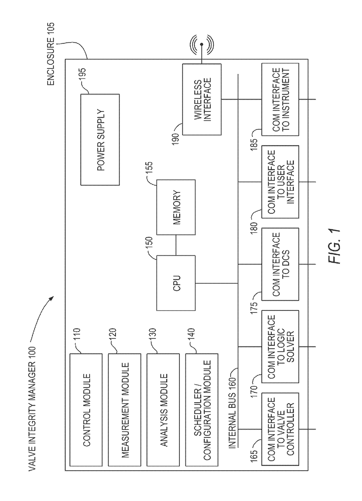
[0021]Referring to FIG. 1, the valve integrity manager 100 comprises an enclosure 105 that houses a central processing unit 150 coupled to non-volatile memory 155. Central processing unit 150 is wired to an internal bus 160, to which is also wired a valve controller communication interface 165, a logic solver communication interface 170, a distributed control system communication interface 175, a user communication interface 180, an instrument communication interface 185, and a wireless interface 190. Non-volatile memory 155 contains four software modules: a control module 110, a measurement module 120, an analysis module 130, and a scheduler / configuration module 140. These software modules are executed by the central processing unit 150.

[0022]Control module 110 directs a micro stroke to either open or close an emergency shutdown valve by a set percentage. For example, if the valve is fully open, control module 110 can perform a micro stroke to close by 2%. In another example, if th...


PUM

PropertyMeasurementUnit
temperatureaaaaaaaaaa
mean time between failuresaaaaaaaaaa
pressureaaaaaaaaaa

Abstract

A valve integrity manager is coupled with a servo or stepper motor to direct micro stroke testing of emergency shutdown valves. During testing, the system orders a closure of 20-25% of an emergency shutdown valve, providing data that either confirms the operability of the valve or a deficiency, while minimizing any effect on process variables.

Description

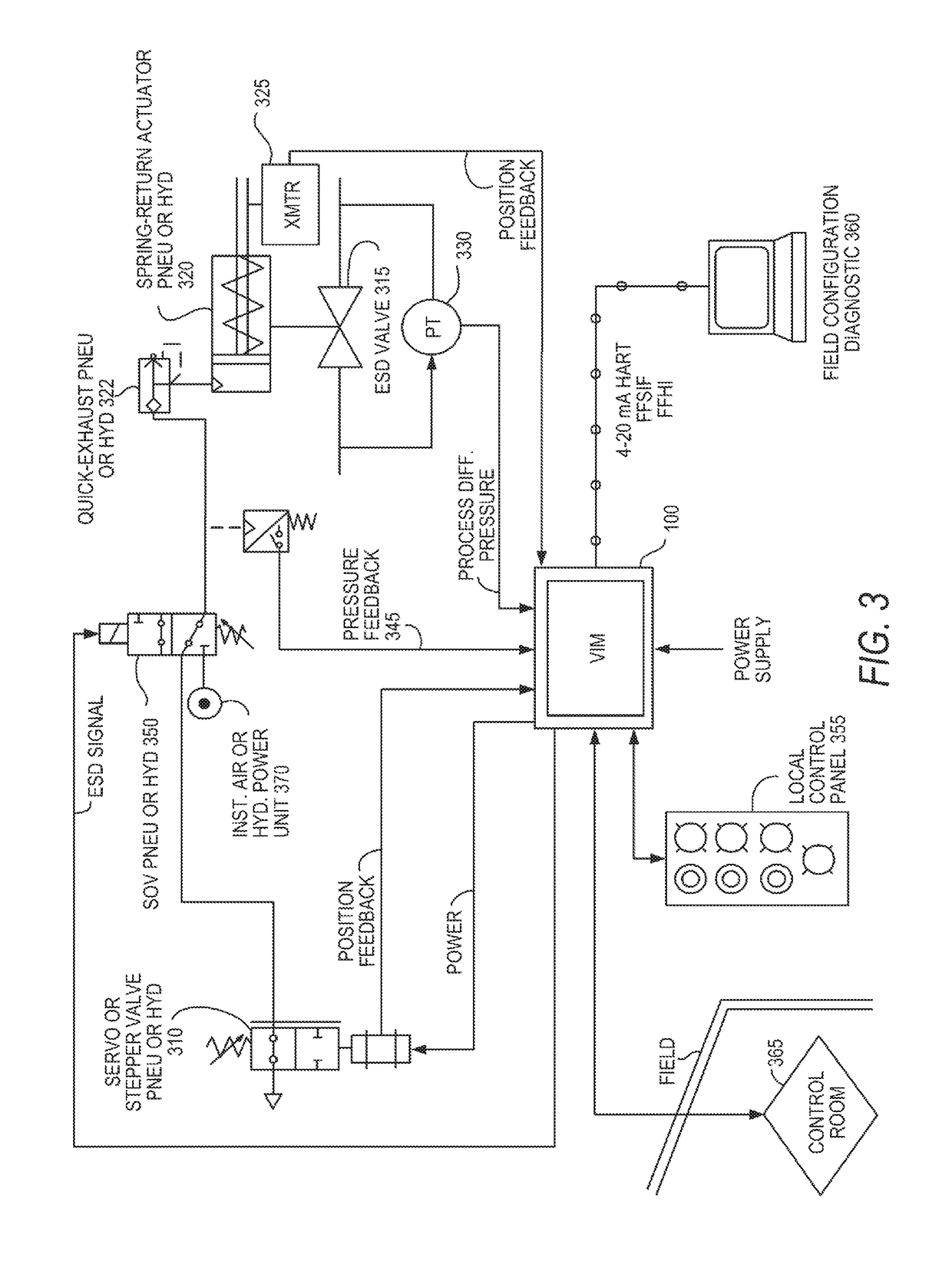
FIELD OF THE INVENTION[0001]The present invention relates to a system to automatically perform micro strokes of emergency shutdown valves. The micro strokes produce a small percentage of the full stroke of the valve, allowing normal process operations to continue while confirming that the valve would respond appropriately to an emergency shutdown command.BACKGROUND OF THE INVENTION[0002]To protect plant equipment and personnel, in addition to protecting neighboring property, people, and the environment, many industrial plants include emergency shutdown (ESD) valves designed to interrupt process flow in the event of an emergency, such as a pipe rupture. ESD valves are actuated valves that operate under fail-safe principles, forming part of a safety instrumented system. An ESD valve actuator drives its associated ESD valve through pneumatic or hydraulic pressure, with energy being stored with a compressed spring (in the case of single-acting actuators) or with energy being stored with...

Claims


Application Information

Patent Timeline
Patent Type & Authority Patents(United States)
IPC IPC(8): G01L27/00F16K37/00F16K17/36F16K31/06
CPCF16K37/005F16K37/0041F16K31/06F16K17/36G05B23/0256F16K37/0083F16K37/0091
Inventor DARAISEH, ABDELGHANIFLANDERS, PATRICK S.SIMEONI, JUAN R.
Owner SAUDI ARABIAN OIL CO
Learn More