
Equipment for measurement and control of load material or scrap feeding into a furnace and relative method

a technology for measuring and controlling equipment and load material, which is applied in the direction of furnaces, furnace monitoring devices, charge manipulation, etc., can solve the problems of reducing the overall efficiency of the productive cycle, prolonging the smelting time in the furnace, and prolonging the whole productive cycl

Active Publication Date: 2018-08-28
TENOVA
View PDF9 Cites 0 Cited by
  • Summary
  • Abstract
  • Description
  • Claims
  • Application Information

AI Technical Summary

Benefits of technology

The aim of the invention is to solve the problems of high costs, limited functionality, and complex operational methods in a simple, economical, and effective way.

Problems solved by technology

In fact, if the continuous addition of load material in solid state is not continuously and correctly controlled, this can cause problems that reduce the overall efficiency of the productive cycle.
Among these problems, the most important is the formation of thickened solid material in the scrap unloading zone in the furnace, as it maintains this consistence for a long period of time, thus prolonging the smelting time in the furnace, and as a result, prolonging the whole productive cycle.
Naturally this operator must be extremely familiar with the process and the installation, and in any case his decisions can still always be affected by uncertain and not very reliable data reading.
However, the furnace shell profile is strictly linked with erosive phenomena that the liquid metal provokes in the refractory, phenomena, which are often violent and unpredictable.
Inevitably with time, this causes a lack of precision in the taring curve used to compare the level reading and the volume calculation.
Considering said lack of precision and the high specific weight of iron, the measured data will reveal quite a large error, and therefore this technique cannot be used for precision control.
Therefore the amount of the load material or scrap metal included constitutes only a limited percentage fraction of the measured weight, and this involves all the various aspects of lack of precision.
This lack of precision becomes so great that any measurements performed can be considered reliable only as far as quality is concerned.

Method used


Image

  • Equipment for measurement and control of load material or scrap feeding into a furnace and relative method
  • Equipment for measurement and control of load material or scrap feeding into a furnace and relative method
  • Equipment for measurement and control of load material or scrap feeding into a furnace and relative method

Examples


Embodiment Construction

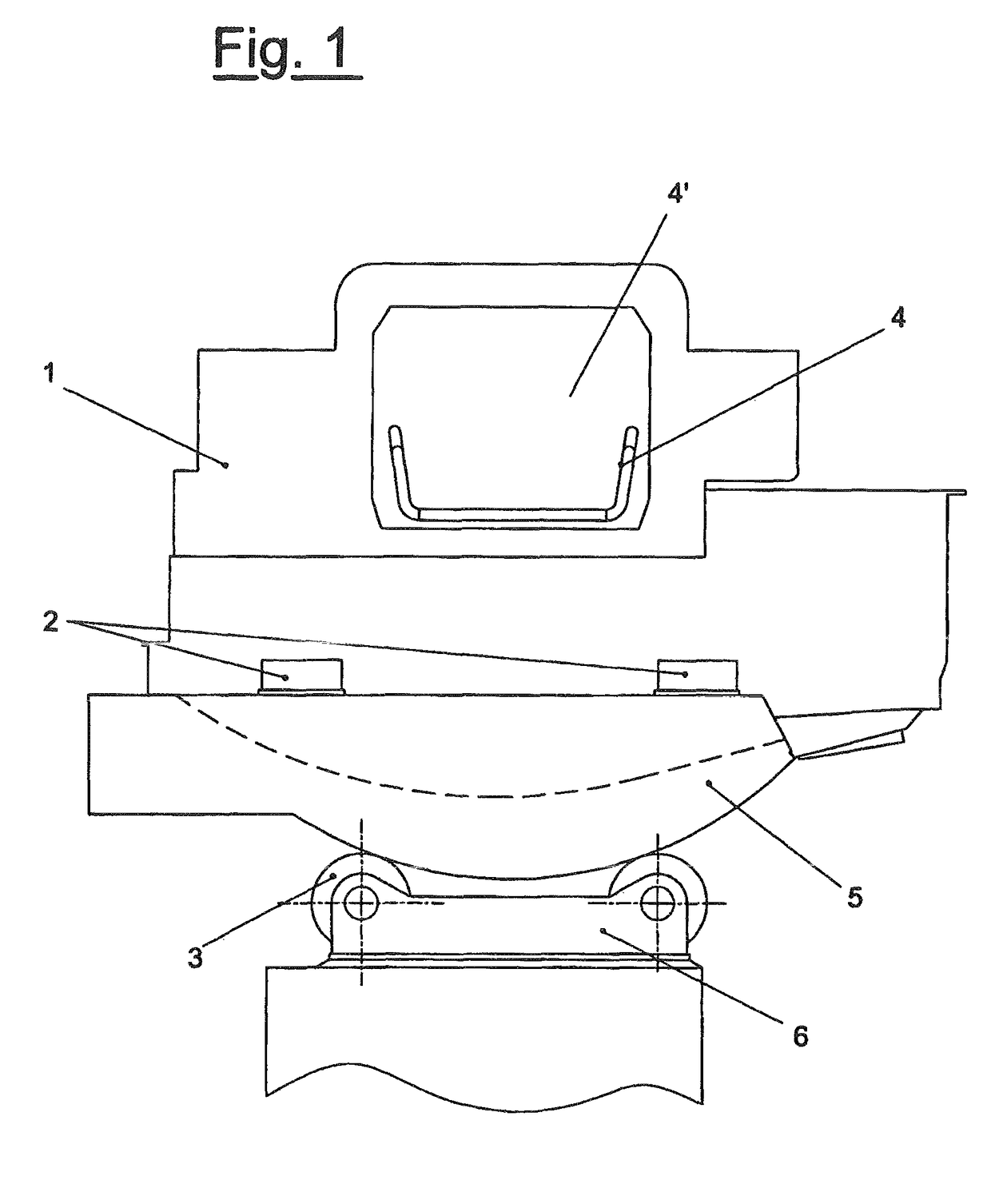
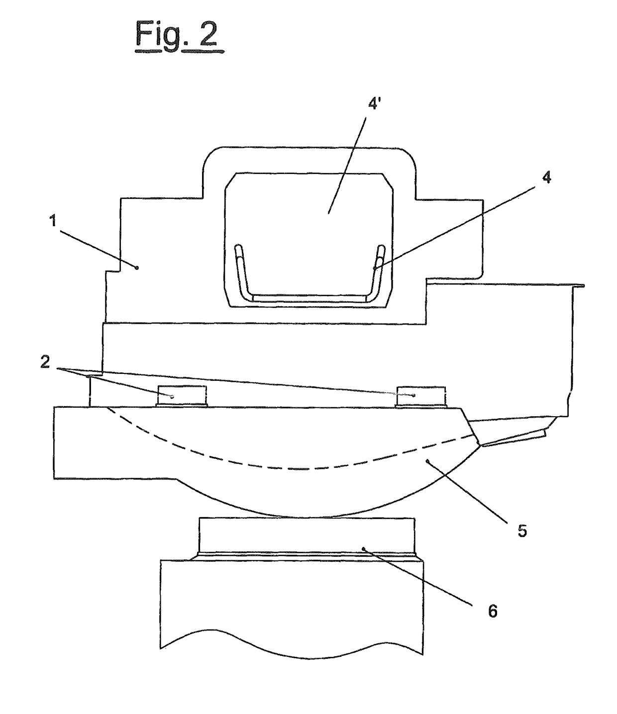
[0058]In particular, FIG. 1 shows an EAF furnace whose tilting platform (5) (for slagging, tapping or emptying operations) is supported by wheels (3) positioned on support bases (6).

[0059]The furnace shell (1) is set by means of suitable supports (2) on the tilting platform (5).

[0060]The side opening (4′) is used to feed the scrap metal, by means of a conveyor (4) if necessary, with a continuous feeding procedure such as that provided by the CONSTEEL® system, for example. The traditional configuration is sometimes equipped with instruments for reading the weight by means of sensors located in the axes of the EAF furnace support wheels (3).

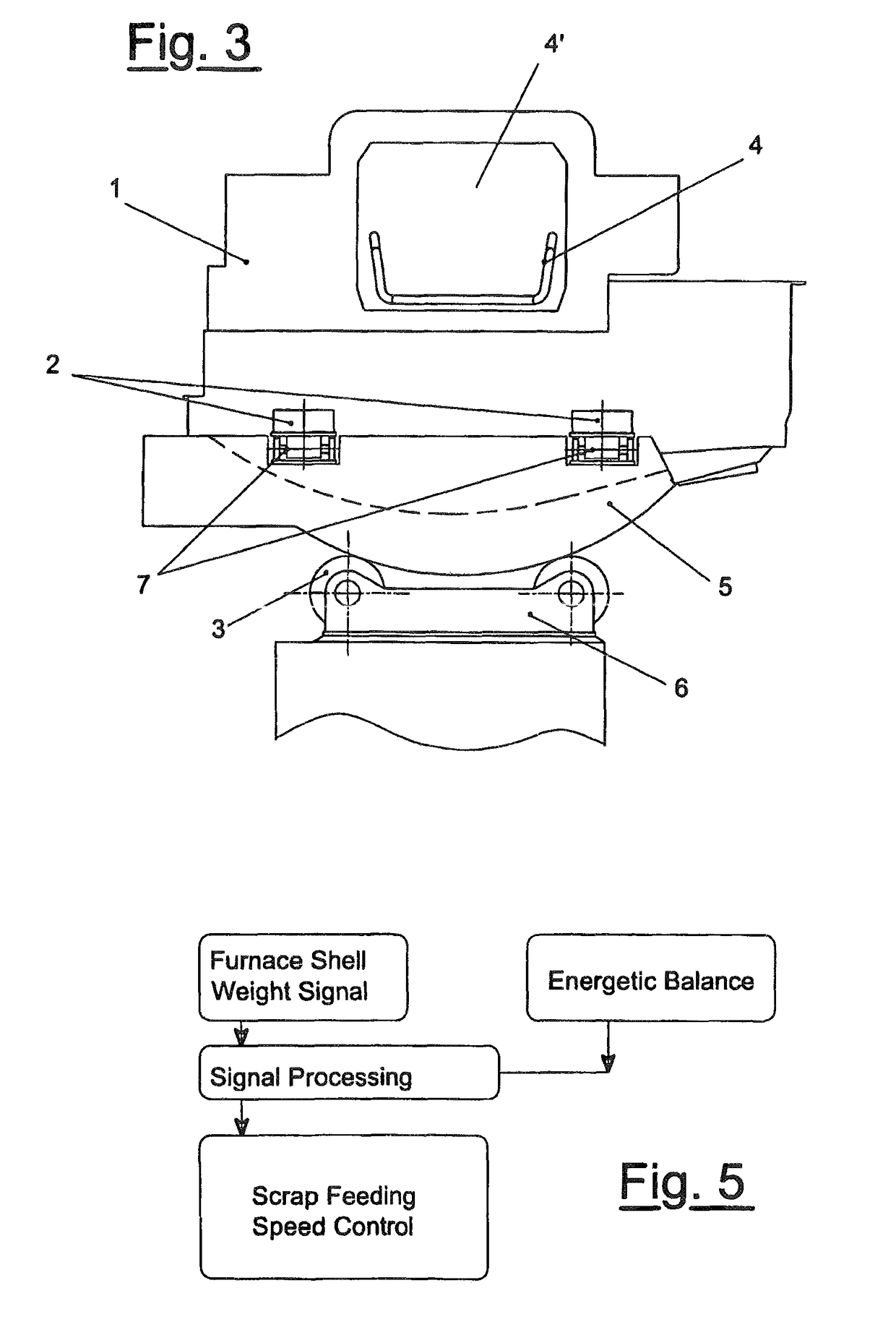
[0061]On the other hand, the embodiment shown in the FIGS. 3 and 4 refers to the invention according to the present invention. The tilting platform (5) is mounted on the support base (6), and the furnace shell (1) is set on suitable supports (2) on the platform. In order to allow for structural settling due to the temperature, the furnace shell sup...


PUM

PropertyMeasurementUnit
energyaaaaaaaaaa
weightaaaaaaaaaa
speedaaaaaaaaaa

Abstract

Equipment for the measurement and control of load material and scrap metal feeding into an electrical arc furnace includes an automatic control device for feeding control of load material or scrap according to the energy supplied to the bath, and a measuring device for the added load material, in correlation with the automatic control device, and a weighing device for the furnace shell, its contents and any other components it may support.

Description

FIELD OF THE INVENTION[0001]The present invention relates to equipment for the measurement and control of feeding load material and scrap into a furnace and the relative method, in particular for the measuring and control of continuous feeding.BACKGROUND OF THE INVENTION[0002]The use of continuous systems for loading scrap metal into a furnace, in particular in an electric arc furnace (EAF) for steel production, systems such as CONSTEEL® for example, and / or the addition of previously reduced material to the bath, involves the need for maintaining direct control of the load material flow as it enters the furnace.[0003]In fact, if the continuous addition of load material in solid state is not continuously and correctly controlled, this can cause problems that reduce the overall efficiency of the productive cycle. Among these problems, the most important is the formation of thickened solid material in the scrap unloading zone in the furnace, as it maintains this consistence for a long ...

Claims


Application Information

Patent Timeline
Patent Type & Authority Patents(United States)
IPC IPC(8): F27D13/00F27B3/28F27B7/28C21B13/12F27D3/00F27D21/00C21C5/52C21C5/56F27B3/18F27D19/00
CPCF27D21/0035C21C5/527C21C5/567F27B3/183F27B3/28F27B7/28F27D3/0024F27D3/0025F27D19/00C21B13/12Y02W30/54C21C2005/5288C21C2300/02F27D2019/0075Y02P10/216Y02P10/20Y02W30/50
Inventor ARGENTA, PAOLOREALI, SILVIOLODATI, CLAUDIOBIANCHI FERRI, MAURO
Owner TENOVA
Learn More