Air disperser for spray-drying, and a method for manufacturing an air disperser comprising metal forming

a technology of air disperser and air forming, which is applied in the field of air dispersers, can solve the problems of relative large number of components to be handled, and the manner of manufacturing air dispersers is relatively cumbersome, and achieve the effect of improving the conditions of manufacture and operation

Active Publication Date: 2018-09-04
GEA PROCESS ENG
View PDF23 Cites 0 Cited by
  • Summary
  • Abstract
  • Description
  • Claims
  • Application Information

AI Technical Summary

Benefits of technology

[0006]It is an object of the invention to provide an air disperser for a spray drying apparatus, in which the conditions of manufacture and operation are improved.
[0008]The invention is based on the recognition that an improved reliability in the quality of the product is achieved by the increased accuracy and predictability in the configuration of the air disperser, which is the result of providing at least some portions of the base module by precision metal forming, Thus, the tendency of deviations of the flow of drying air is reduced, thus eliminating or at least reducing the risk of product deposits emanating from an asymmetric flow, which in turn could affect the quality of the dried product. The air disperser according to the invention may be manufactured with a high degree of predictability, and the reproducibility in the configuration entails that the variations between individual air dispersers are substantially lower than in prior art devices including manufacture and assembly of a larger number of components. This, in turn, compensates for the larger investment in tools and machinery required by the precision metal forming as compared to the traditional manufacture and assembly. The advantages obtained by the present invention are particularly pronounced in smaller spray drying plants.
[0011]The precision metal forming may in principle be chosen from any type rendering it possible to obtain the required accuracy and hence improved flow of drying air. In a further development of the preferred embodiment, each of the lower portion and the upper portion are formed by metal spinning.
[0012]Metal spinning typically does not have the versatility of other metal forming techniques, such as deep drawing or pressing. Due to the nature of the process, metal spinning cannot create irregular shapes; however, for bell-shaped, spherical, and tubular forms, metal spinning is often highly cost-efficient. This is not a result of the high fixed cost of metal spinning, but of the relatively low variable costs. Due to the nature of metal spinning, an absolutely rotational-symmetric item is produced, which is of great importance for the object in question.
[0015]In a second aspect, a method for improving the flow of drying air in a spray drying apparatus.

Problems solved by technology

Thus, a relatively large number of components need to be handled and connected to each other.
Although these air dispersers provide for reliable operation, the manner of manufacturing the air disperser is relatively cumbersome and entails some disadvantages due to in particular the assembly.
In addition to the resources expenses, the manufacture of the individual components, each with a particular tolerance, and the subsequent assembly including the welding necessarily entail that deviations from a model configuration and from one air disperser to the other occur.

Method used


Image

  • Air disperser for spray-drying, and a method for manufacturing an air disperser comprising metal forming
  • Air disperser for spray-drying, and a method for manufacturing an air disperser comprising metal forming
  • Air disperser for spray-drying, and a method for manufacturing an air disperser comprising metal forming

Examples


Embodiment Construction

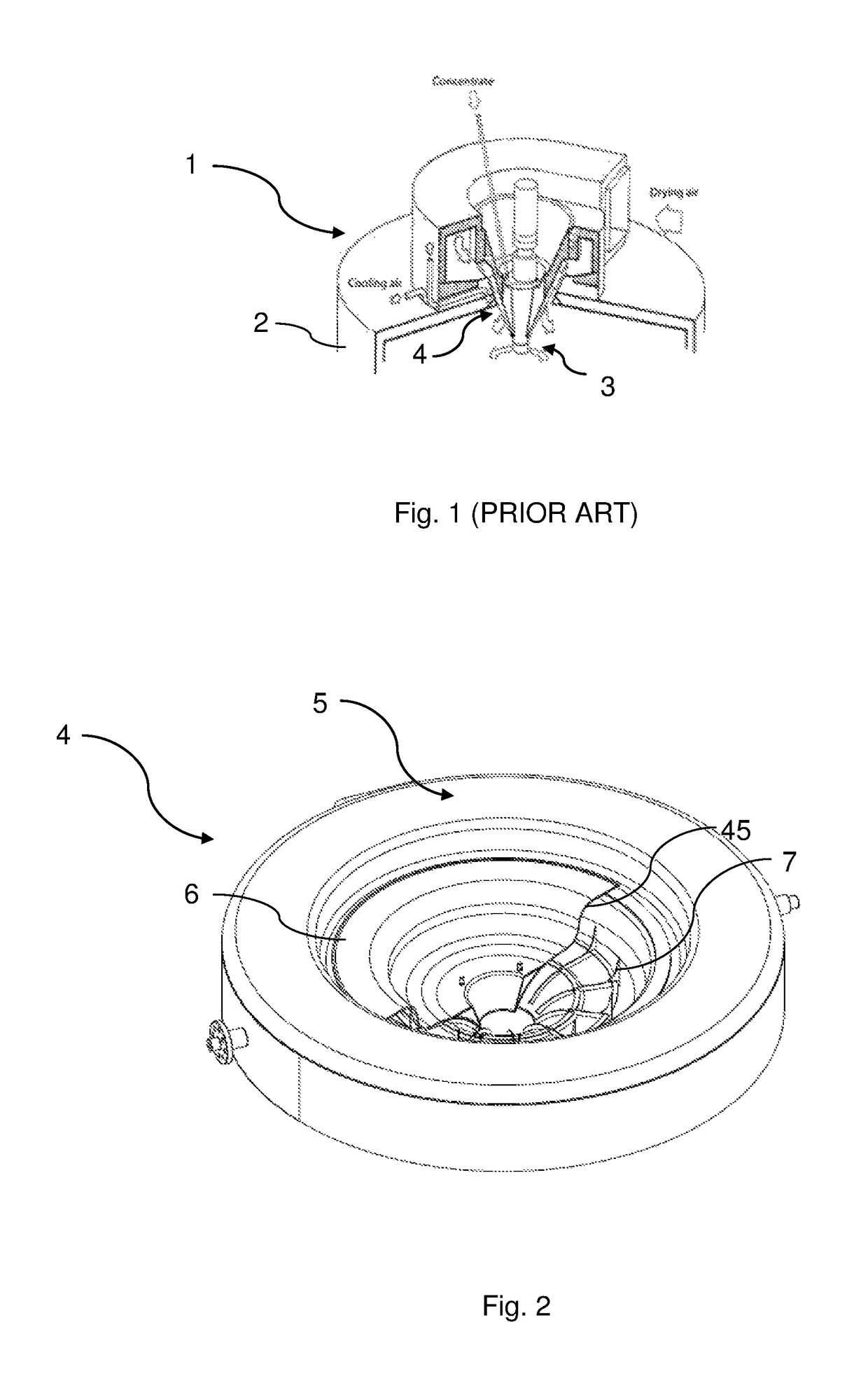
[0025]In FIG. 1, relevant parts of the top of a prior art spray drying apparatus generally designated 1 are shown. The spray drying apparatus 1 comprises a drying chamber 2 to which a feed to be spray dried is introduced at the top thereof by means of suitable atomizing means 3 and is set into a, possibly swirling, downward movement in the drying chamber 2 by drying air introduced via an air disperser generally designated 4 mounted at the ceiling of the drying chamber 2 of the spray drying apparatus. The spray drying apparatus may for instance form part of a spray drying plant in which further components are present, in which the drying process and other processes associated with the drying of materials are carried out.

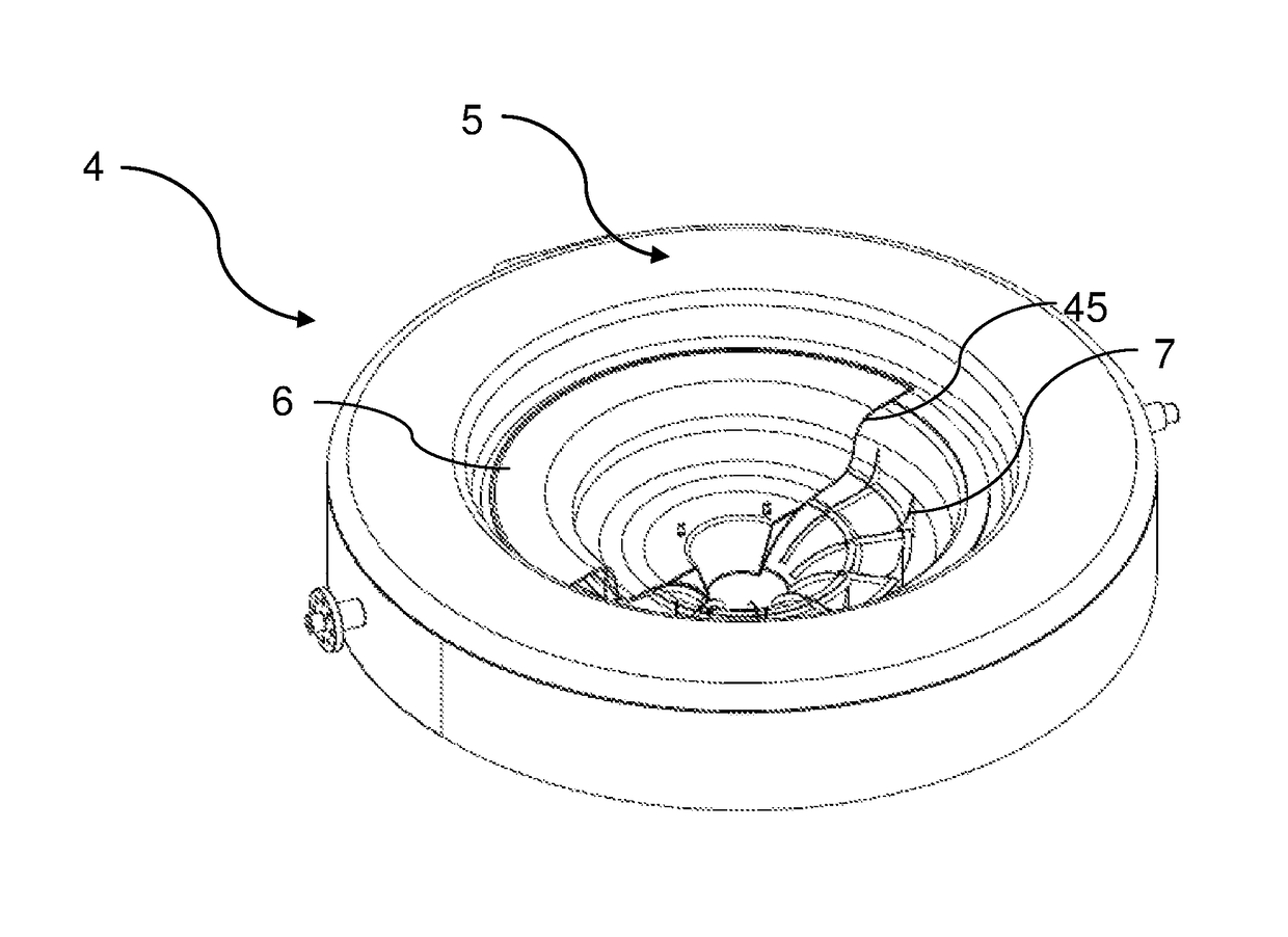
[0026]Referring now to FIGS. 2 to 10, a first embodiment of an air disperser designated 4 according to the present invention will be described in some detail. It is noted that parts of a spray drying apparatus, in which the air disperser according to the invention is ...


PUM

PropertyMeasurementUnit
diameteraaaaaaaaaa
diameteraaaaaaaaaa
inner radiusaaaaaaaaaa

Abstract

In the air disperser (4) having a number of components including a top, a bottom and an outer circumferential wall forming a space (45) defined within an inner radius and an outer radius and having an air inlet (81), a set of guide vanes (7), and an air outlet (82) at the inner radius adapted to be positioned above a feed outlet from atomizing means, at least some of the components are formed by precision metal forming such as metal spinning.

Description

CROSS REFERENCE TO RELATED APPLICATIONS[0001]This application is the National Stage Entry under 35 U.S.C. § 371 of Patent Cooperation Treaty Application No. PCT / DK2014 / 050160, filed 4 Jun. 2014 the contents of which are hereby incorporated by reference herein.FIELD OF THE INVENTION[0002]The present invention relates to an air disperser for a spray drying apparatus, comprising a number of components including a top, a bottom and an outer circumferential wall forming a space defined within an inner radius and an outer radius and having an air inlet, a set of guide vanes, and an air outlet at said inner radius adapted to be positioned above a feed outlet from atomizing means. The invention furthermore relates to a method for improving the flow of drying air in a spray drying apparatus.BACKGROUND OF THE INVENTION[0003]In general, spray drying may be performed in many ways, and to all varieties it applies that the air distribution in the spray drying apparatus is one of the most vital pa...

Claims


Application Information

Patent Timeline
Patent Type & Authority Patents(United States)
IPC IPC(8): F26B21/00B21D22/14F26B3/12B05B1/26B01D1/18F26B21/14
CPCF26B21/004B01D1/18F26B21/14B21D22/14F26B3/12B05B1/26
Inventor NIELSEN, KENT LUCKSTADT
Owner GEA PROCESS ENG
Why Eureka
Try Eureka