High-temperature superconducting high-current devices compensated for anisotropic effects
a high-current device and superconducting technology, applied in the field of electromagnetism, can solve the problems of inherently limited current-carrying capacity of power transmission cables and may not be optimal for prior art use,
- Summary
- Abstract
- Description
- Claims
- Application Information
AI Technical Summary
Benefits of technology
Problems solved by technology
Method used
Image
Examples
first embodiment
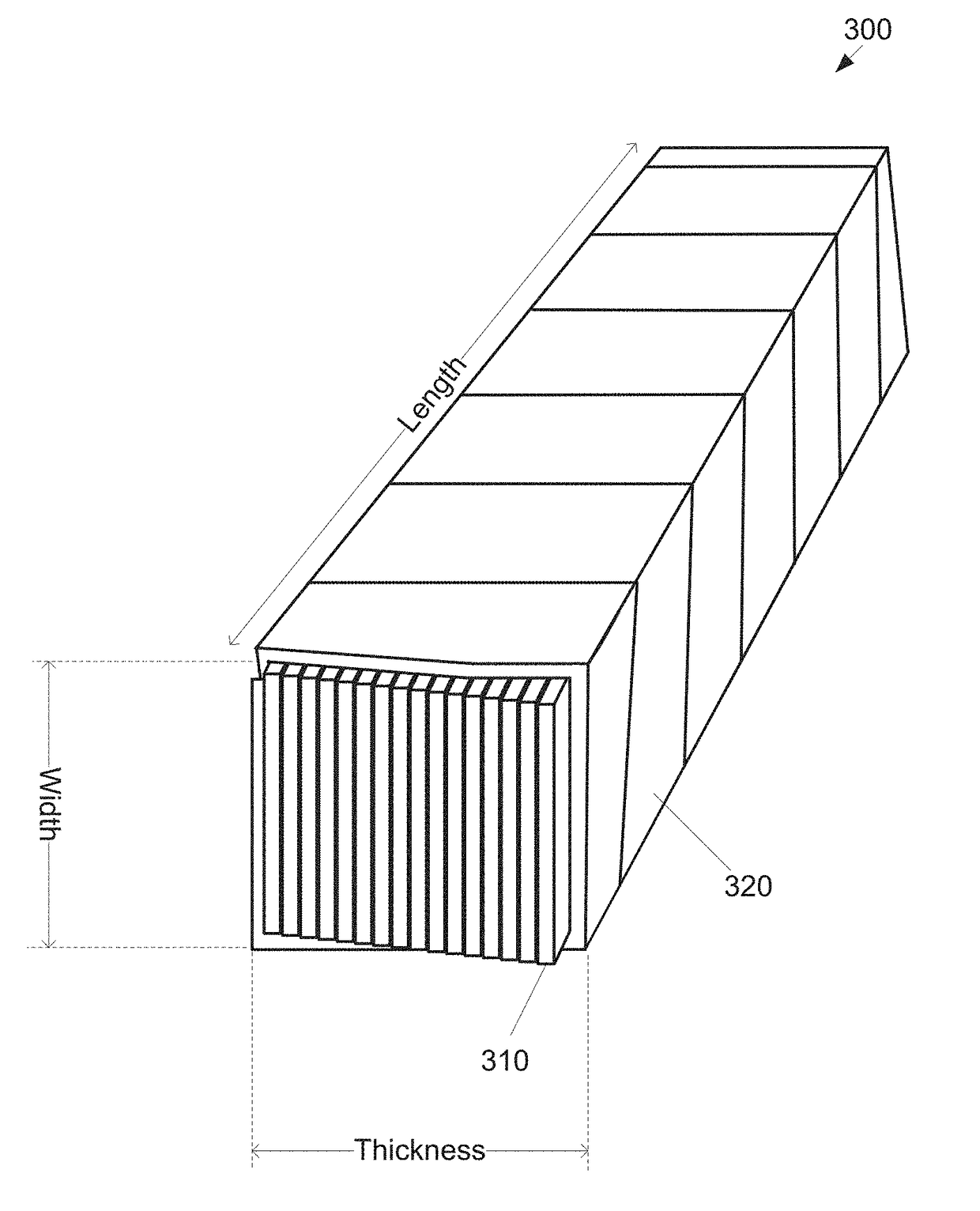
[0045]The subassembly wrapper 320 is wrapped around the stack of tapes 310, for example, with windings of a wrapper material forming the subassembly wrapper 320 wound in a helical fashion around the cable subassembly 300 for substantially the length of the cable subassembly 300. The subassembly wrapper 320 may be formed of wire or tape wrapping material formed of a conducting material, for example, copper, or a non-conducting or insulating material, for example, stainless steel. In the first embodiment, the subassembly wrapper 320 is not formed of a superconducting material. The windings of the subassembly wrapper 320 may overlap, may abut, or may have a gap between successive windings. Other subassembly wrapper 320 configurations are also possible, for example, a braided wire or tape wrapping. The subassembly wrapper 320 may be relatively thin with respect to the dimensions of the tapes 310, for example, a subassembly wrapper 320 formed of copper on the order of 25 μm thick.
[0046]I...
second embodiment
[0053]The cable assembly wrapper 420 may be formed of wire wrapping or tape wrapping material formed of a conducting material, for example, copper, or a non-conducting or insulating material, for example, stainless steel. In the second embodiment, the cable assembly wrapper 420 is not formed of a superconducting material. The windings of the cable assembly wrapper 420 may overlap, may abut, or there may be a gap between successive windings. Other wrapping configurations are also possible, for example, a braided wire wrapping or tape wrapping. The cable assembly wrapper 420 may be relatively thin, for example, a formed of copper on the order of 25-μm thick.
[0054]Under the second embodiment, the cable subassemblies 300 are arranged so that the tapes 310 (FIG. 3) within each of the cable subassemblies 300 within the cable assembly 400 are similarly oriented with respect to one another. In a preferred embodiment, the cable subassemblies 300 in the cable assembly 400 are not soldered tog...
third embodiment
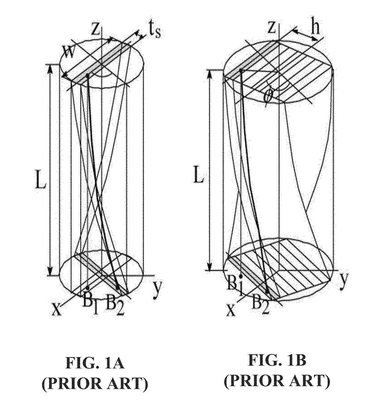
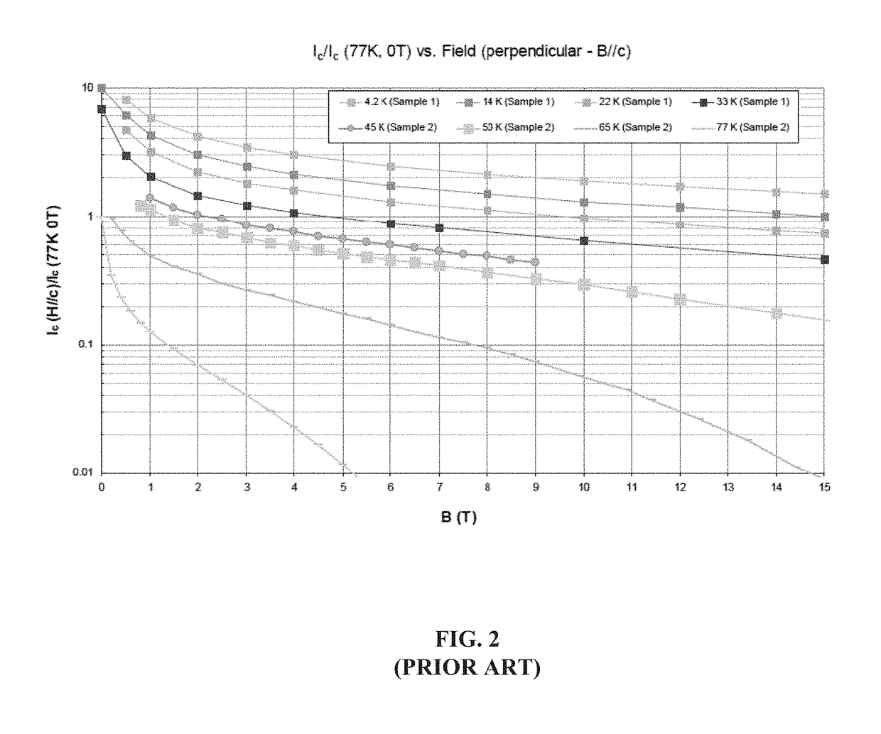
[0059]The superconducting capacity of a cable assembly 400 increases according to the number of subassemblies 300 used in the cable assembly 400. However, the superconducter capacity may not increase proportionally according to the number of subassemblies 300 being used, due to capacity degradation by anisotropy of the magnetic field, particularly when the cable assembly 400 is formed into a solenoid. The anisotropic effect may be mitigated somewhat by using a subassembly 600 according to a HTS-HC, shown in FIGS. 6A-6C. As noted above, the strong magnetic field is substantially parallel to the wide surface of the superconducting tape. The magnetic field impinges upon the superconductor perpendicular to the wide surface, reducing the carrying capacity of the superconductor tape.
[0060]As shown by FIGS. 6A-6C, under the third embodiment, a cable assembly 600 may include multiple cable subassemblies 610, 620 having two distinct orientations with respect to the superconductor tapes. Cabl...
PUM
| Property | Measurement | Unit |
|---|---|---|
| width | aaaaa | aaaaa |
| critical current | aaaaa | aaaaa |
| current level | aaaaa | aaaaa |
Abstract
Description
Claims
Application Information
 - R&D
- Intellectual Property
- Life Sciences
- Materials
- Tech Scout
- Unparalleled Data Quality
- Higher Quality Content
- 60% Fewer Hallucinations
Browse by: Latest US Patents, China's latest patents, Technical Efficacy Thesaurus, Application Domain, Technology Topic, Popular Technical Reports.
© 2025 PatSnap. All rights reserved.Legal|Privacy policy|Modern Slavery Act Transparency Statement|Sitemap|About US| Contact US: help@patsnap.com


