
Multilayer capacitor and mounting structure

a multi-layer capacitor and mounting structure technology, applied in the direction of fixed capacitor details, feed-through capacitors, fixed capacitors, etc., can solve problems such as vibration sound on the substra

Active Publication Date: 2018-09-18
KYOCERA CORP
View PDF4 Cites 4 Cited by
  • Summary
  • Abstract
  • Description
  • Claims
  • Application Information

AI Technical Summary

Benefits of technology

This design effectively suppresses acoustic noise by preventing solder fillet formation on the external electrodes, thereby minimizing vibration transmission to the substrate, enhancing noise suppression and preventing structural issues like the tombstone phenomenon.

Problems solved by technology

Due to the vibration transmitted to the substrate, resonance occurs in the substrate with consequent amplification of the vibration, thus causing vibration sound in the substrate.

Method used


Image

  • Multilayer capacitor and mounting structure
  • Multilayer capacitor and mounting structure
  • Multilayer capacitor and mounting structure

Examples


embodiment

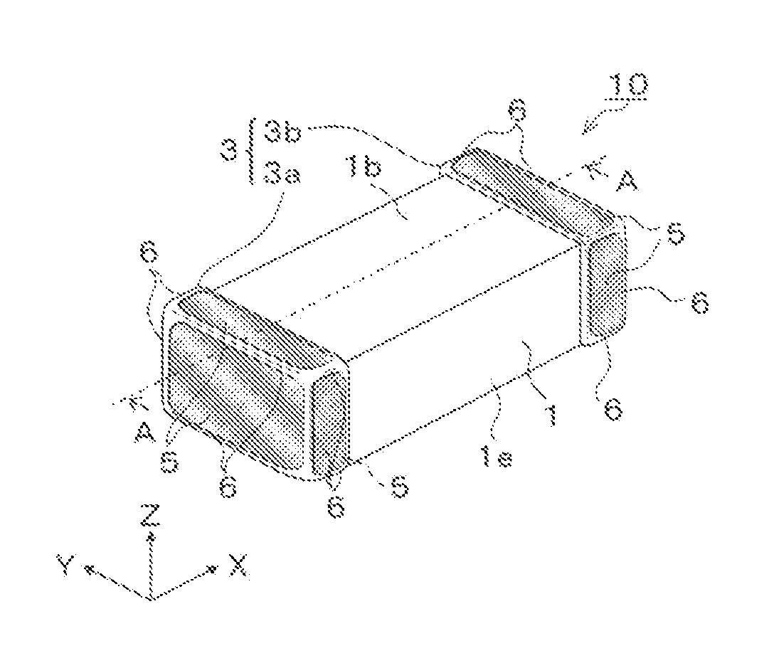
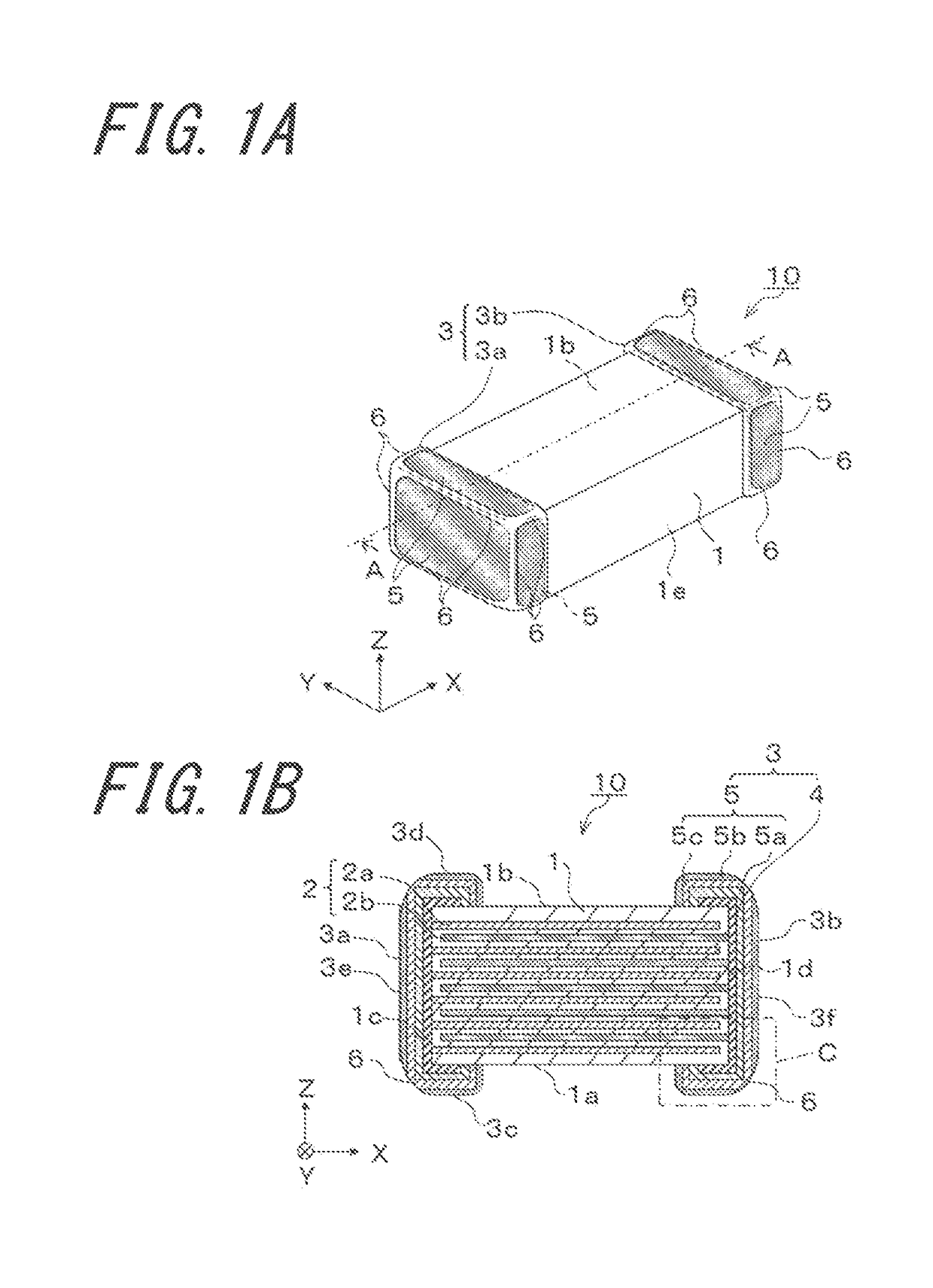
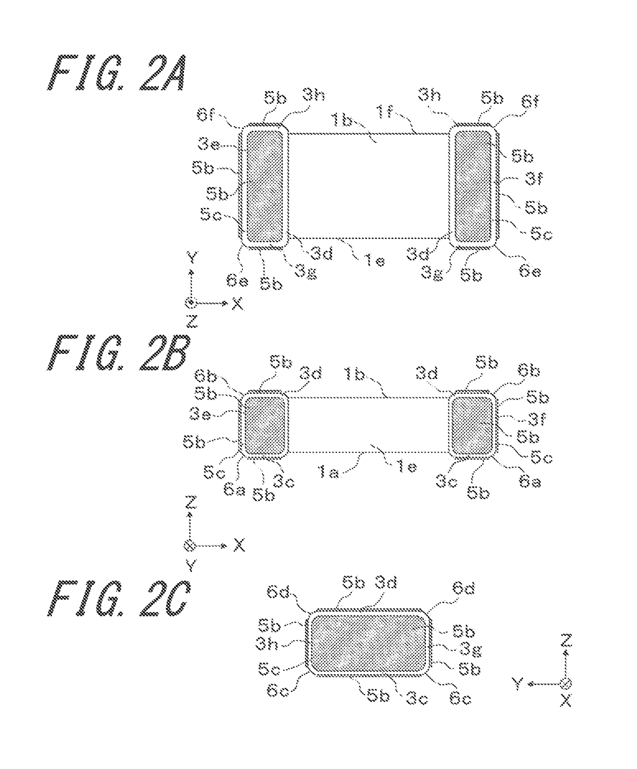
[0015]Hereinafter, a multilayer capacitor 10 in accordance with an embodiment of the invention will be described with reference to drawings.

[0016]FIG. 1A is a schematic perspective view showing a multilayer capacitor 10 in accordance with an embodiment of the invention. The multilayer capacitor 10 comprises: dielectric layers made of a ceramic material and internal electrodes 2 (first internal electrodes 2a and second internal electrodes 2b) that are alternately laminated; and a pair of external electrodes (a first external electrode 3a and a second external electrode 3b) electrically connected to the internal electrode 2 extracted to a first end face 1c and the internal electrode 2 extracted to a second end face 1d, respectively. That is, of the internal electrodes 2, the first internal electrode 2a is electrically connected to the first external electrode 3a, and the second internal electrode 2b is electrically connected to the second external electrode 3b. Moreover, for the sake ...


PUM

PropertyMeasurementUnit
thicknessaaaaaaaaaa
thicknessaaaaaaaaaa
thicknessaaaaaaaaaa

Abstract

A multilayer capacitor includes a pair of external electrodes each having an end face portion; a first principal face extending portion; a second principal face extending portion; a first side face extending portion; and a second side face extending portion. The pair of external electrodes each includes a base electrode and a metallic layer. The metallic layer includes a first metallic layer and a second metallic layer located outside the first metallic layer. An intermetallic compound layer is located outside the first metallic layer, and is exposed from the second metallic layer in a ridge portion lying between the end face portion and the first principal face extending portion, a ridge portion lying between the first side face extending portion and the first principal face extending portion, and a ridge portion lying between the second side face extending portion and the first principal face extending portion.

Description

TECHNICAL FIELD[0001]The present invention relates to a multilayer capacitor, and more particularly to a multilayer capacitor comprising a stacked body in which a plurality of dielectric layers and internal electrodes are alternately laminated, and a mounting structure thereof.BACKGROUND ART[0002]In a multilayer capacitor, dielectric layers and internal electrodes are alternately laminated, and in general, a ferroelectric material having a relatively high dielectric constant, such as barium titanate, is used as a ceramic material which constitutes the dielectric layer. When an AC voltage is applied to such a multilayer capacitor, distortion occurs in the dielectric layer due to an electrostrictive effect of the ceramic material, and the multilayer capacitor in itself vibrates. The vibration of the multilayer capacitor is transmitted to a substrate mounting the multilayer capacitor via solder or other means. Due to the vibration transmitted to the substrate, resonance occurs in the s...

Claims


Application Information

Patent Timeline
Patent Type & Authority Patents(United States)
IPC IPC(8): H01G4/30H01G4/232H01G4/008H01G2/06H01G4/35H01G4/12
CPCH01G4/30H01G2/06H01G4/232H01G2/065H01G4/008H01G4/12H01G4/306H01G4/2325
Inventor HATANAKA, HIDEFUMIKATO, KATSUICHI
Owner KYOCERA CORP
Learn More