Apparatus for measuring a tubular string as it is lowered into a borehole and method

a technology of tubular string and apparatus, which is applied in the direction of instruments, surveying, borehole/well accessories, etc., can solve the problems of many human errors in the manual process, and achieve the effects of preventing slippage, promoting positive engagement, and preventing slippag

Active Publication Date: 2018-09-25
ACCU TALLY
View PDF16 Cites 4 Cited by
  • Summary
  • Abstract
  • Description
  • Claims
  • Application Information

AI Technical Summary

Benefits of technology

[0012]In one embodiment of the apparatus of the present invention, the rotation of each of the plurality of rotating members is monitored by a rotation sensor. The rotation sensor generates a signal to a processor, the signal corresponding to sensed rotations of a rotating member. Each rotating member may not rotate at the same rate or through the same number of rotations as other rotating members of the apparatus. Misalignment of the tubular string within the central passage may cause a rotating member on a first lower leg to lose positive engagement with the tubular string while a rotating member on a second, adjacent lower leg may remain in positive engagement with the tubular string. The processor may receive a plurality of signals from the plurality of rotation sensors disposed to monitor the plurality of rotating members. The processor may be programmed to compare the number of rotations and / or the rate of rotation of each of the plurality of rotating members, as indicated by the plurality of signals, occurring during a time interval and to determine which of the rotating members had positive engagement with the tubular string during that time interval. For example, but not by way of limitation, in an embodiment of the apparatus of the present invention having three rotating members and three rotation sensors, each disposed to sense the number of rotations of a rotating member, a processor may compare the three signals corresponding to the sensed rotations of the rotating members and the processor may be programmed to select the signal corresponding to the rotation sensor with the highest number of rotations or with the highest rate of rotation. The selected signal and rotation sensor would then be designated as being the rotating member having the most positive engagement with the tubular string. It will be understood that, generally speaking, the rotating member with the greatest rate of rotation or the greatest number of rotations within a given time interval is the rotating member having the most positive engagement with the tubular string. The processor may continually or intermittently repeat this determination in order to adjust to changes such as the position of the tubular string within the central passage through the apparatus. In this manner, the accuracy of the apparatus in determining the length and profile of the tubular string being run into or removed from a wellbore is increased.
[0014]In one embodiment, each of the plurality of rolling elements includes a periphery that is shaped to promote positive engagement with the tubular string. For example, but not by way of limitation, the periphery of a rolling element may include a portion that is generally parallel to the axis about which the rolling element rotates, a first side at an obtuse angle to the generally parallel portion, and a second side at an equally obtuse angle to the generally parallel portion to form a trough. The trough-shaped periphery of the rolling element may be shaped and sized to engage the tubular string with both the first side and the second side to provide more positive engagement between the rolling element and the tubular string and to prevent slippage that may compromise the measurements taken by the apparatus.
[0020]It will be understood that the rotating assembly engages the exterior surface of the tubular string with the rolling elements which may be comprised of steel or other common structural materials. In one embodiment, the dynamic responsiveness of the rolling elements can be enhanced by the use of a very lightweight material with a correspondingly low inertia. It will be understood that a rolling element that comprises a very low density material will minimize the amount of force needed to displace the rolling element from a first position to a second position as would occur when at a diameter transition in the tubular string.

Problems solved by technology

This manual process is exposed to many opportunities for human error.

Method used


Image

  • Apparatus for measuring a tubular string as it is lowered into a borehole and method
  • Apparatus for measuring a tubular string as it is lowered into a borehole and method
  • Apparatus for measuring a tubular string as it is lowered into a borehole and method

Examples


Embodiment Construction

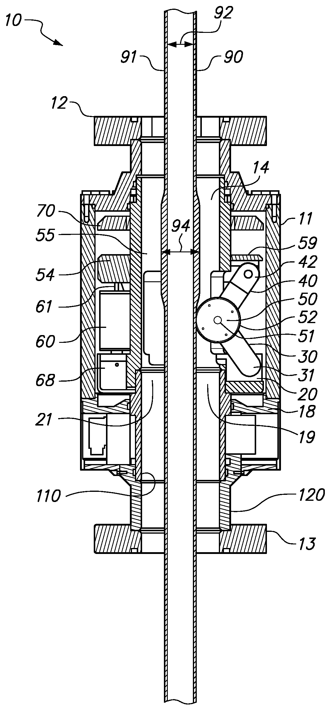
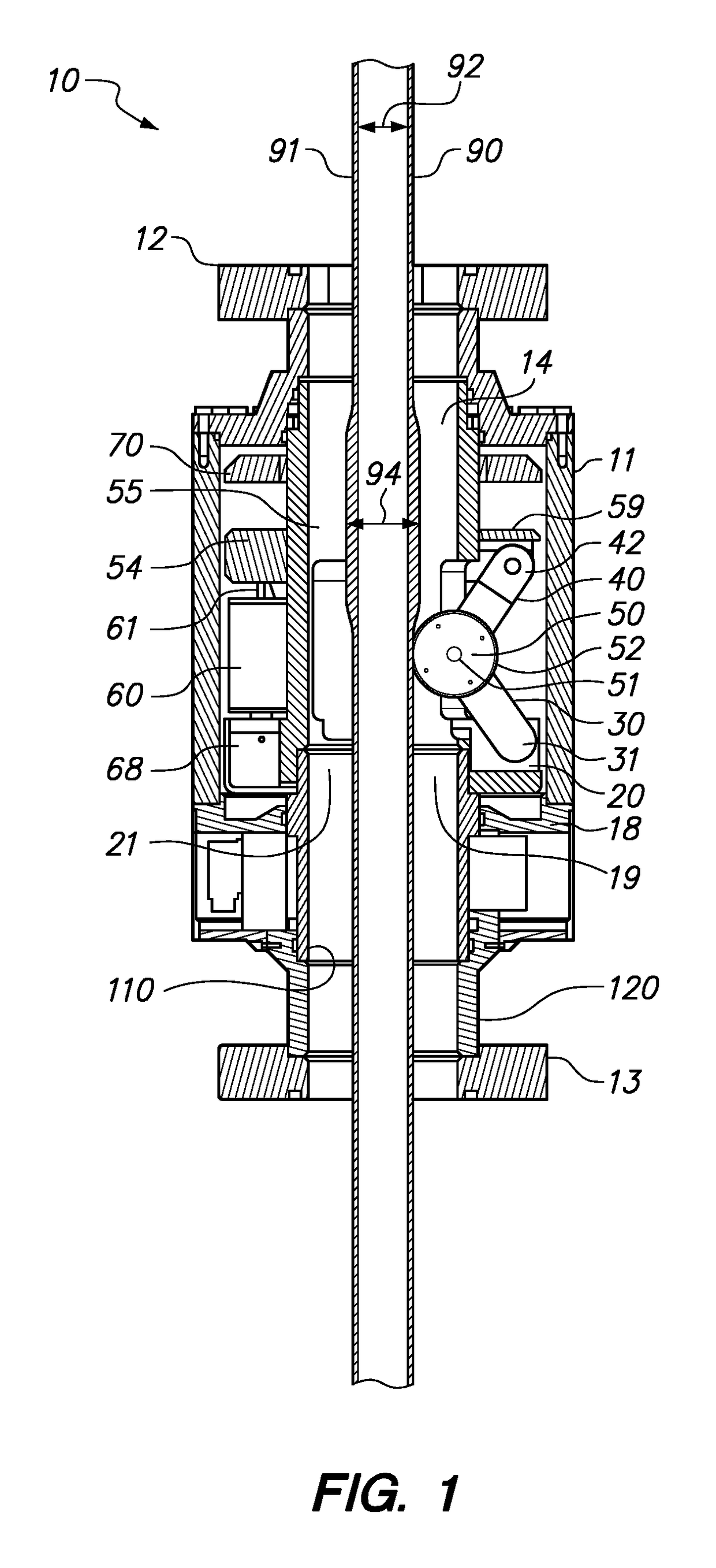
[0030]FIG. 1 is a sectional elevation view of an embodiment of an apparatus 10 of the present invention with a tubular string 90 having an interior diameter 92 extending therethrough. The apparatus 10 comprises a housing 11 having an upper flange 12 and a lower flange 13, and in interior chamber 14 therebetween. The housing 11 includes an annular support 18 having a central passage 19. A lower ring 20 is rotatably supported on the annular support 18 and includes a central passage 21 that is aligned with the central passage 19 of the annular support 18. An upper ring 54 also includes a central passage 55 that is aligned with the central passages 19 and 21 of the annular support 18 and the lower ring 20, respectively. The apparatus 10 further comprises a plurality of angularly distributed rolling elements 50.

[0031]The lower ring 20 is pivotally coupled to a plurality of angularly distributed lower legs 30 at a first end 31 of each of the plurality of lower legs 30, and the upper ring ...


PUM


Abstract

An apparatus for measuring a profile of a tubular string and the components thereof as the tubular string is made up and run into a borehole. The apparatus includes a rotating assembly disposed within a housing, the rotating assembly including a plurality of upper legs, and plurality of lower legs and a plurality of rolling elements, each upper leg having a proximal end and a distal end coupled to an upper ring, each lower leg having a proximal end coupled to a lower ring and a distal end, and each rolling element rotatably coupled to the proximal end of an upper leg and a distal end of a lower leg. The apparatus further includes a sensor for detecting a position of the rolling elements as they engage an exterior surface of a tubular string being made up and run into a borehole from a rig. The apparatus receives the tubular string through aligned central passages in the upper ring, lower ring and the rotating assembly.

Description

BACKGROUNDField of the Invention[0001]The present invention relates to equipment used for oil and gas drilling. More specifically, the present invention relates to a method and equipment for measuring components of a tubular string as it is made up and run into a borehole.Background of the Related Art[0002]A well may be drilled into the earth's crust for recovery of hydrocarbons, such as oil and gas, from a geologic formation. Various kinds of tubular components are instrumental in constructing and operating a hydrocarbon recovery well. A tubular string is formed by joining tubular segments of a particular type end to end. A borehole is drilled using a drill string comprising tubular drill pipe segments. A bottom-hole assembly (BHA) having a drill bit may be provided at the distal end of the drill string, and the borehole is formed by rotating the drill bit to extend the borehole into the earth's crust. The tubular drill string includes an interior bore that allows drilling fluid to...

Claims


Application Information

Patent Timeline
Patent Type & Authority Patents(United States)
IPC IPC(8): E21B47/04G01D5/252E21B47/00E21B47/09G01B5/10
CPCE21B47/09G01D5/252E21B47/04E21B47/00
Inventor WILLIAMS, CHARLES M.JORDAN, LANCE C.SMITH, KEVIN J.BURNS, JR., PATRICK A.MAXFIELD, DAVIDPHELPS, PHILLIPBENDITZ, DALE
Owner ACCU TALLY
Why Eureka
Try Eureka