Material for and the method of manufacture for ballistic shielding

a technology of ballistic shielding and material, applied in the field of equipment, can solve the problems of providing no or negative acoustic protection, difficult etc., and achieve the effect of facilitating the mitigation of lead hazards, easy installation, replacement or repair

Inactive Publication Date: 2018-09-25
SHOTSTOP BALLISTICS LLC
View PDF30 Cites 2 Cited by
  • Summary
  • Abstract
  • Description
  • Claims
  • Application Information

AI Technical Summary

Benefits of technology

[0015]It is an advantage of the present invention to provide ballistic protection curtains that provide primary impact protection from fired rounds.
[0016]It is another advantage of the present invention to provide ballistic protection curtains that provide secondary impact protection to prevent hazardous stray or ricochet projectiles.
[0017]It is yet another advantage of the present invention to provide a replacement for steel plates, baffles or cladding in the protection of exposed surfaces throughout an indoor shooting range.
[0018]It is still yet another advantage of the present invention to provide acoustic attenuation within an indoor shooting range.
[0019]It is yet still other advantages of the present invention to provide a device and system that lighter than conventional solutions, can be made to include various colors or aesthetics, and are difficult to install, replace or repair.
[0020]Further, it is an advantage of the present invention to facilitate the mitigation of a lead hazard associated with the continuous destruction of lead projectiles.

Problems solved by technology

While the use of metal baffles and cladding provide effective ballistic protection, they are heavy, unattractive, provide no or negative acoustic protection, and are difficult to install, replace or repair.
Further, the use of metal baffles and cladding can facilitate a lead hazard associated with the continuous destruction of lead projectiles.

Method used


Image

  • Material for and the method of manufacture for ballistic shielding
  • Material for and the method of manufacture for ballistic shielding
  • Material for and the method of manufacture for ballistic shielding

Examples


Embodiment Construction

[0031]The best mode for carrying out the invention is presented in terms of its preferred embodiment, herein depicted within the Figures.

1. Detailed Description of the Figures

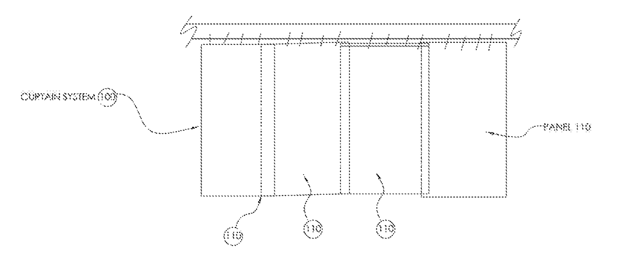
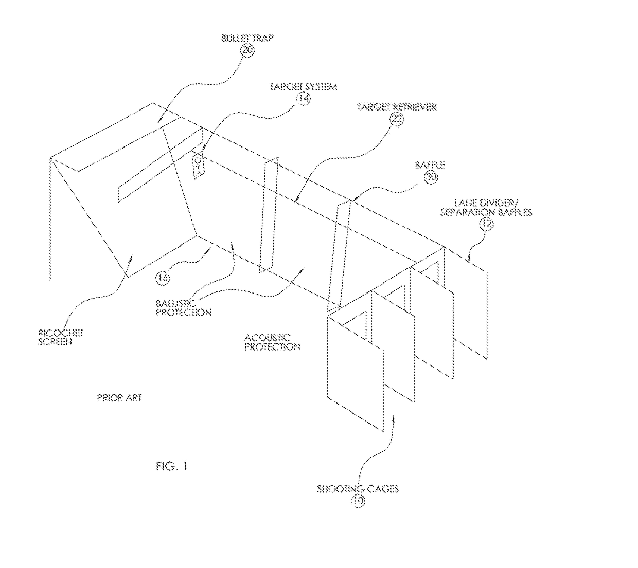
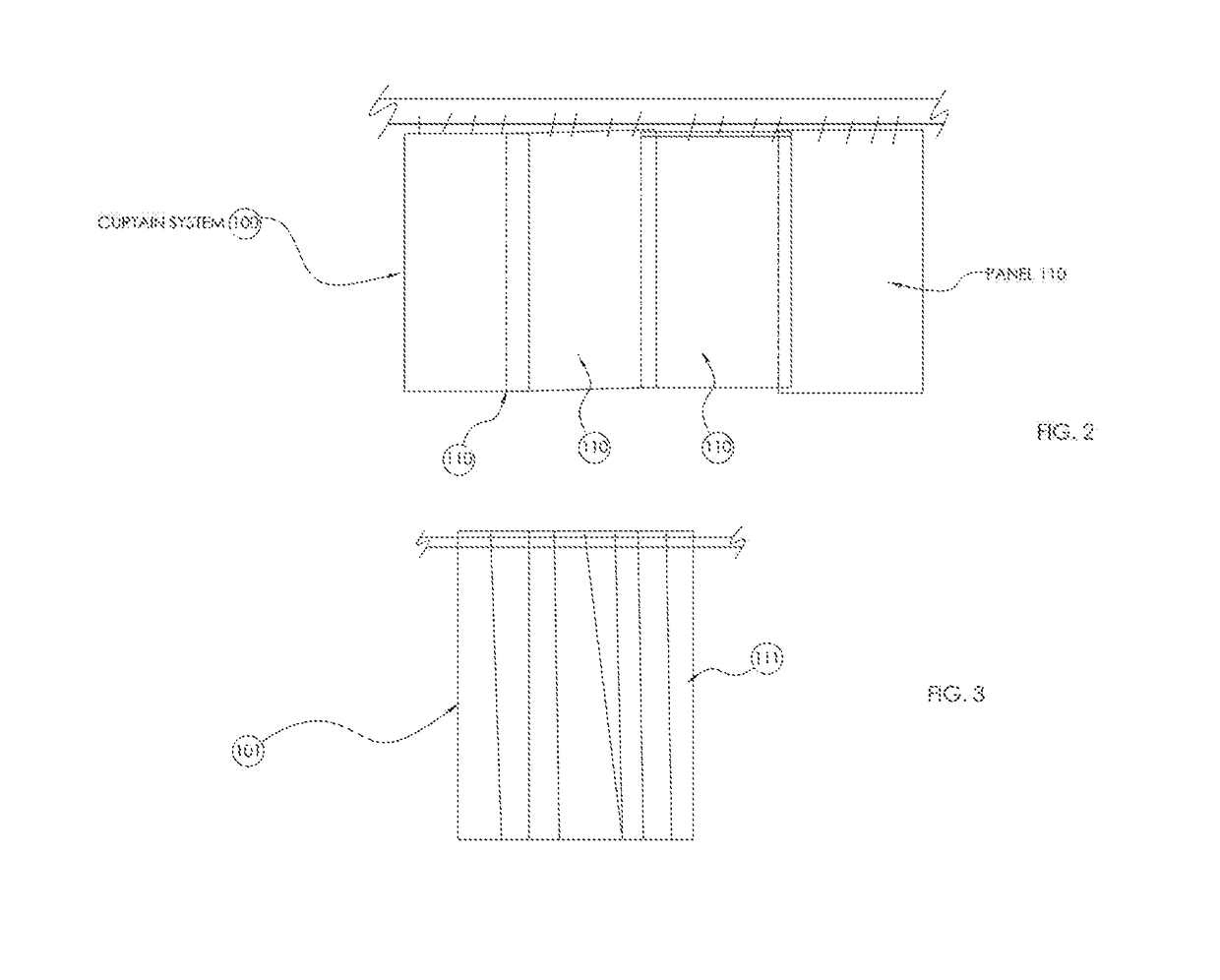
[0032]Referring now to the Figures, a ballistic resistant curtain system is provided, generally noted as 100, according to a preferred embodiment of the present invention. The curtain system 100 is formed of a plurality of individual ballistic material panels 110 that are aligned such as to provide a surface having a generally contiguous line of sight covering for nonballistic surfaces. Each ballistic material panel 110 is formed of an improved composite ballistic material. The panels 110 may be of a variety of configurations, such as the larger panels 110 positioned abutted to or slightly overlaped with adjacent panels, as shown best in FIG. 2. One potential alternate configuration may include a vertical blind type of arrangement 101 formed of much narrower panels strips 111 as best shown in FIG. 3. No matter ...


PUM

PropertyMeasurementUnit
thicknessaaaaaaaaaa
mechanical tensionaaaaaaaaaa
melting pointaaaaaaaaaa

Abstract

A ballistic resistant curtain system is provided formed of a plurality of aligned ballistic material panels. Panels protect vertical surfaces, and can be reconfigured for horizontal surfaces or other oriented areas. Adjacent panels may be are aligned end to end in a butt or overlap manner, or configured to be angularly disposed toward the direction of fire such as to form a line of sight overlap. Each panel is formed of high strength fibers made from materials such as extended chain ultra-high molecular weight polyethylene. An exterior coating formed of fabric, polyurethane, or other material provides both an acoustic attenuation or sound absorbing surface as well as an aesthetic facing for providing an improved visual appearance to the area. The instant abstract is neither intended to define the invention disclosed in this specification nor intended to limit the scope of the invention in any way.

Description

RELATED APPLICATIONS[0001]The present invention is a Continuation in Part application of U.S. Ser. No. 14 / 701,326, filed on Apr. 30, 2015 and which was a continuation in part of U.S. Ser. No. 13 / 219,920, filed on Aug. 29, 2011 and now U.S. Pat. No. 9,180,623, both of which are incorporated by reference as if fully rewritten herein.BACKGROUND OF THE INVENTION1. Field of the Invention[0002]This invention relates generally to equipment utilized in the operation of indoor shooting ranges and, more particularly, to a ballistic resistant curtain system formed of an improved composite ballistic material.2. Description of the Related Art[0003]Indoor shooting ranges typically have similar layouts to incorporate standard safety devices and systems, and slightly different from outdoor shooting ranges. Because of the enclosed space, indoor shooting ranges need to be concerned with lane divider safety, ricochet mitigation, and acoustic protection.[0004]A typical indoor shooting range layout is d...

Claims


Application Information

Patent Timeline
Patent Type & Authority Patents(United States)
IPC IPC(8): B23K37/00F41J11/02F41H5/04B32B5/12B32B5/26B32B27/12
CPCF41J11/02F41H5/0471B32B5/12B32B5/26B32B27/12B32B2307/54B32B2571/02B32B2307/558B32B2307/10B32B3/06B32B5/022B32B5/024B32B5/026B32B9/007B32B9/047B32B2250/42B32B2255/02B32B2255/26B32B2260/021B32B2260/04B32B2262/0253B32B2262/0261B32B2307/546B32B2307/706B32B2307/732B32B2307/762B32B2419/00B32B2607/00F41H5/0485F41J13/00
Inventor ILIEV, VALL
Owner SHOTSTOP BALLISTICS LLC
Why Eureka
Try Eureka