
Integrated quartz MEMS tuning fork resonator/oscillator

a technology of tuning fork resonator and quartz, which is applied in the direction of piezoelectric/electrostrictive devices, device material selection, piezoelectric/electrostrictive devices, etc., can solve the problems of reducing accuracy, increasing the power of the overall system, and difficult implementation of prior art techniques

Active Publication Date: 2018-10-23
HRL LAB
View PDF167 Cites 12 Cited by
  • Summary
  • Abstract
  • Description
  • Claims
  • Application Information

AI Technical Summary

Benefits of technology

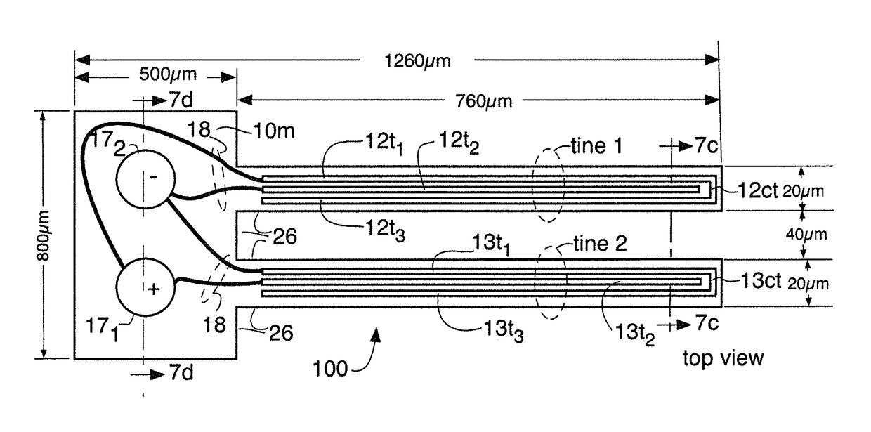
The present invention provides a piezoelectric quartz tuning fork resonator that can be integrally formed on a semiconductor substrate. The resonator includes a pair of tines formed from a common quartz plate, with metal electrodes formed on the tine's surfaces and interconnections disposed in the quartz plate. When an AC current is applied to the metal electrodes, the tines vibrate in response. The resonator can be easily manufactured and integrated onto a semiconductor substrate, which makes it ideal for use in various electronic devices.

Problems solved by technology

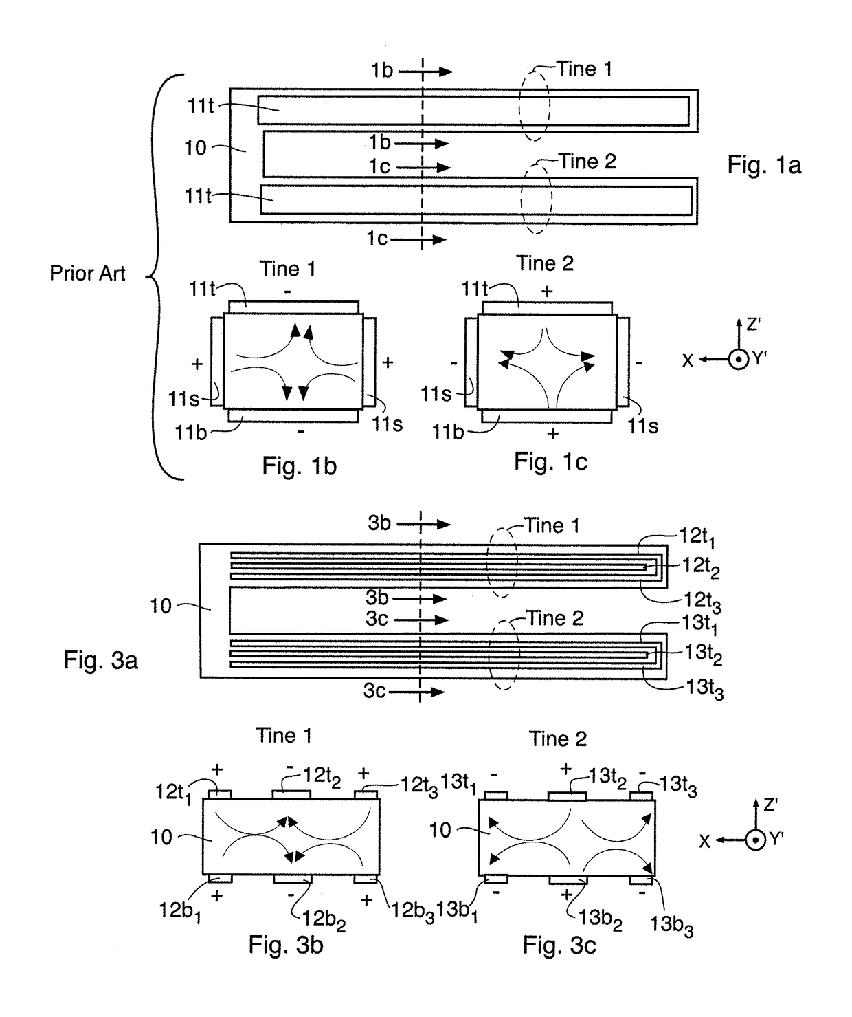
However, resonators operating at such lower frequencies are typically tuning-fork resonators (for which prior art designs are typically 2-10 mm in length) rather than the shear mode slabs used with MHz oscillators.
For some applications, where a combination of both analog and digital systems are utilized and time synchronization is critical for the various RF subsystems, e.g., for GPS or inertial navigation applications, the phase noise and jitter of a kHz clock generated by a prior art tuning-fork resonator can reduce the accuracy and increase the power of the overall system.
This can be due to frequency drift of the energy-efficient microprocessor's clock between clock cycles requiring more extensive processing during the update for re-synchronization.
However, this prior art technique is difficult to implement when a wafer-level process is used and when the quartz resonators are bonded to an underlying handle wafer.
When using a handle wafer, it is difficult to cleanly define the side electrodes while obtaining uniform step coverage and no overcoating of handle wafer itself.
During the release of the resonators from the handle wafer, any overcoated metal can tear from electrodes 11s on the sidewalls of the tines, thus resulting in a low yield.
In addition, using prior art processes, the integration of a kHz clock with other components was not possible.

Method used


Image

  • Integrated quartz MEMS tuning fork resonator/oscillator
  • Integrated quartz MEMS tuning fork resonator/oscillator
  • Integrated quartz MEMS tuning fork resonator/oscillator

Examples


Embodiment Construction

[0024]A detailed description follows. Common reference numerals are for multiple embodiments where the reference numerals refer either to identical or nearly identical structure in the various embodiments or to structure which performs identical or very similar functions in the various embodiments.

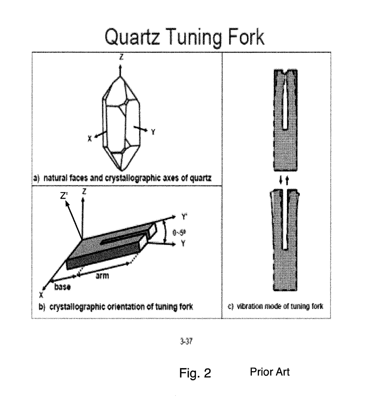
[0025]For the cut angle shown in part b) of FIG. 2 of quartz (commonly called a Z-cut), the component of the electric field in the +X direction produces a contraction in the dimension in the Y′ length of the tines while the component of the electric field in the −X direction produces an extension in the dimension in the Y′ length of the tine. Thus, in both the prior art tuning fork resonator of FIGS. 1a-1c and the tuning fork of the present invention as exemplified by the embodiment of FIGS. 3a-3c, a tuning fork vibrational mode is generated for the two tines which reduces acoustical energy loss to the mounts and yields a high Q or quality factor. By fabricating the tines using plasma etch...


PUM


Abstract

A piezoelectric quartz tuning fork resonator having a pair of tines formed from a common quartz plate, with a middle electrode and two outer electrodes being disposed at or on top and bottom surfaces of each of the pair of tines and interconnected such that the outer electrodes at or on the top and bottom surfaces of a first one of the pair of tines are connected in common with the middle electrodes on the top and bottom surfaces of a second one of the pair of tines and further interconnected such that the outer electrodes at or on the top and bottom surfaces of the second one of the pair of tines are connected in common with the middle electrodes on the top and bottom surfaces of the first one of the pair of tines.

Description

CROSS REFERENCE TO RELATED APPLICATIONS[0001]This application is related to (i) U.S. Pat. No. 7,750,535 issued to Randall L. Kubena et al. on Jul. 6, 2010 and entitled “Quartz-based Nanoresonator” and (ii) U.S. Pat. No. 7,647,688 to David T. Chang et al. on Jan. 19, 2010 and entitled “Method of fabricating a low frequency quartz resonator”, the disclosures of these two U.S. patents are hereby incorporated herein by reference.STATEMENT REGARDING FEDERALLY SPONSORED RESEARCH OR DEVELOPMENT[0002]NoneTECHNICAL FIELD[0003]This invention relates to an integrated quartz tuning fork resonator / oscillator which can are preferably made using Micro Electro Mechanical Systems (MEMS) techniques. The disclosed tuning fork mode resonator / oscillator can operate in a kHz frequency range (for example, a kHz range from 10 kHz to 100 kHz) which is a much lower frequency range than found in shear mode resonators / oscillators which operate in a MHz range (typically at HF, VHF or UHF frequencies).BACKGROUND...

Claims


Application Information

Patent Timeline
IPC IPC(8): H03H9/215H01L41/047H01L41/09H01L41/18H03H9/125H03H3/02
CPCH03H9/215H03H9/125H03H3/02H03H2003/026H03H9/0547H03H9/1021H03H9/13
Inventor KUBENA, RANDALL L.
Owner HRL LAB
Learn More