Electric brake device
a technology of brake device and brake rotor, which is applied in the direction of brake system, mechanical equipment, transportation and packaging, etc., can solve the problems of excessive increased cost and space, and increased wear of brake rotor
- Summary
- Abstract
- Description
- Claims
- Application Information
AI Technical Summary
Benefits of technology
Problems solved by technology
Method used
Image
Examples
Embodiment Construction
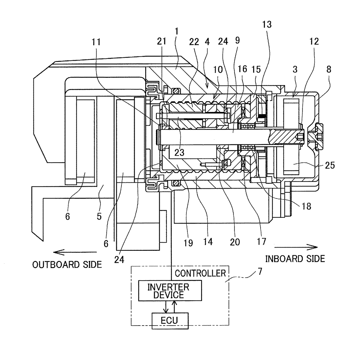
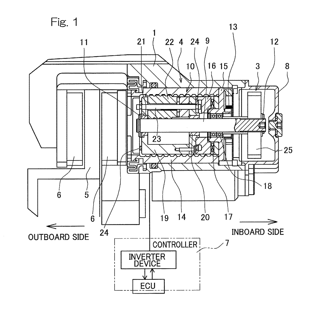
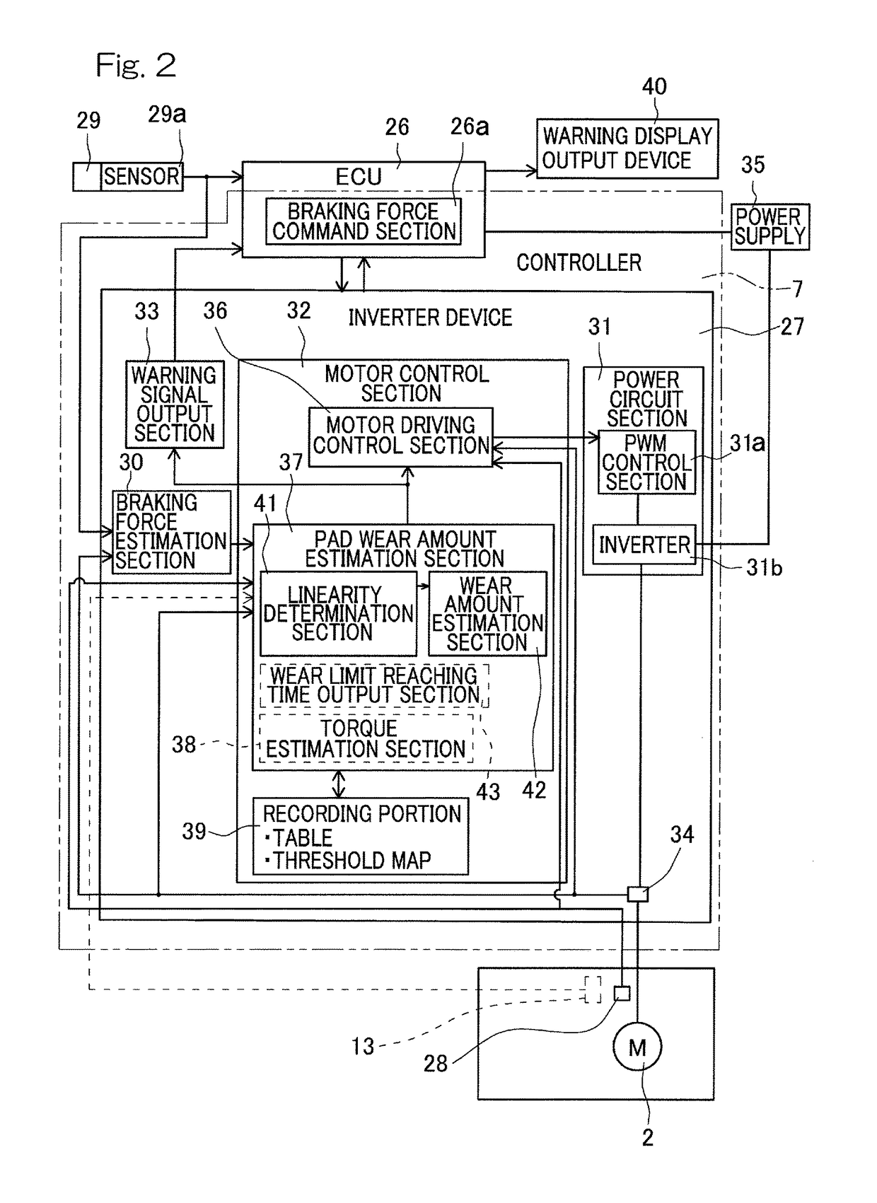
[0048]An electric brake device according to an embodiment of the present invention will be described with reference to FIGS. 1 to 8. As shown in FIG. 1, the electric brake device includes a housing 1, an electric motor 2 (FIG. 2), a speed reduction mechanism 3 that reduces the speed of rotation of the electric motor, a linear motion mechanism 4 serving as a transmission mechanism, a brake rotor 5, a friction pad 6, a locking mechanism (not shown), and a controller 7 that controls the electric motor. The electric motor is supported by the housing 1. The linear motion mechanism 4 is incorporated into the housing 1 so as to apply a braking force to the brake rotor 5 (to a disc rotor in this example) by an output from the electric motor. The housing 1 has an opening end covered by a cover 8.
[0049]The linear motion mechanism 4 will now be described. The linear motion mechanism 4 is a mechanism that converts a rotary motion outputted from the speed reduction mechanism 3 into a linear moti...
PUM
 Abstract
Description
Claims
Application Information
 - R&D
- Intellectual Property
- Life Sciences
- Materials
- Tech Scout
- Unparalleled Data Quality
- Higher Quality Content
- 60% Fewer Hallucinations
Browse by: Latest US Patents, China's latest patents, Technical Efficacy Thesaurus, Application Domain, Technology Topic, Popular Technical Reports.
© 2025 PatSnap. All rights reserved.Legal|Privacy policy|Modern Slavery Act Transparency Statement|Sitemap|About US| Contact US: help@patsnap.com


