

Biomimetic interface device and methods of using the same
- Summary
- Abstract
- Description
- Claims
- Application Information
AI Technical Summary
Benefits of technology
Problems solved by technology
Method used
Image

Examples
Embodiment Construction
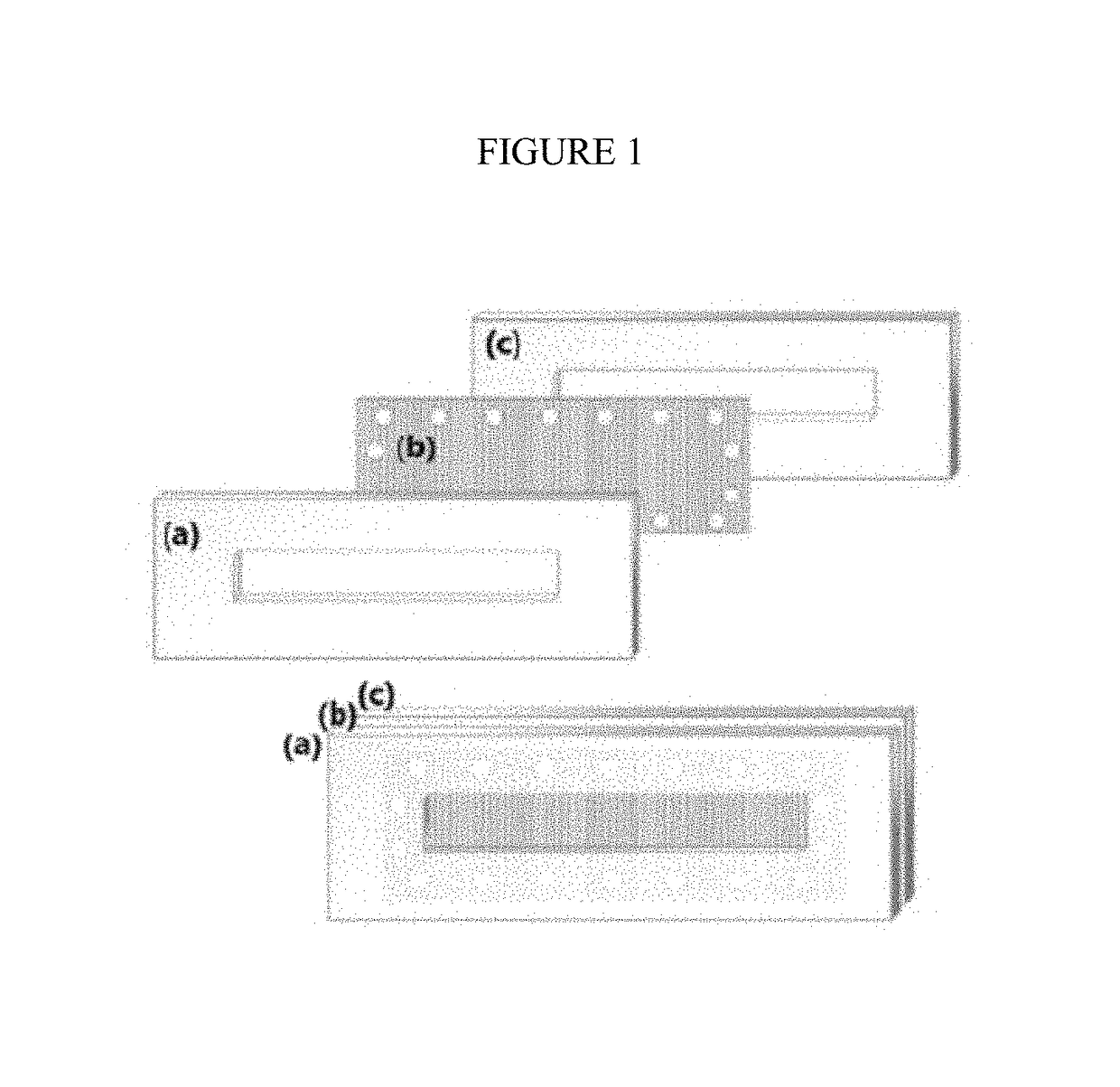
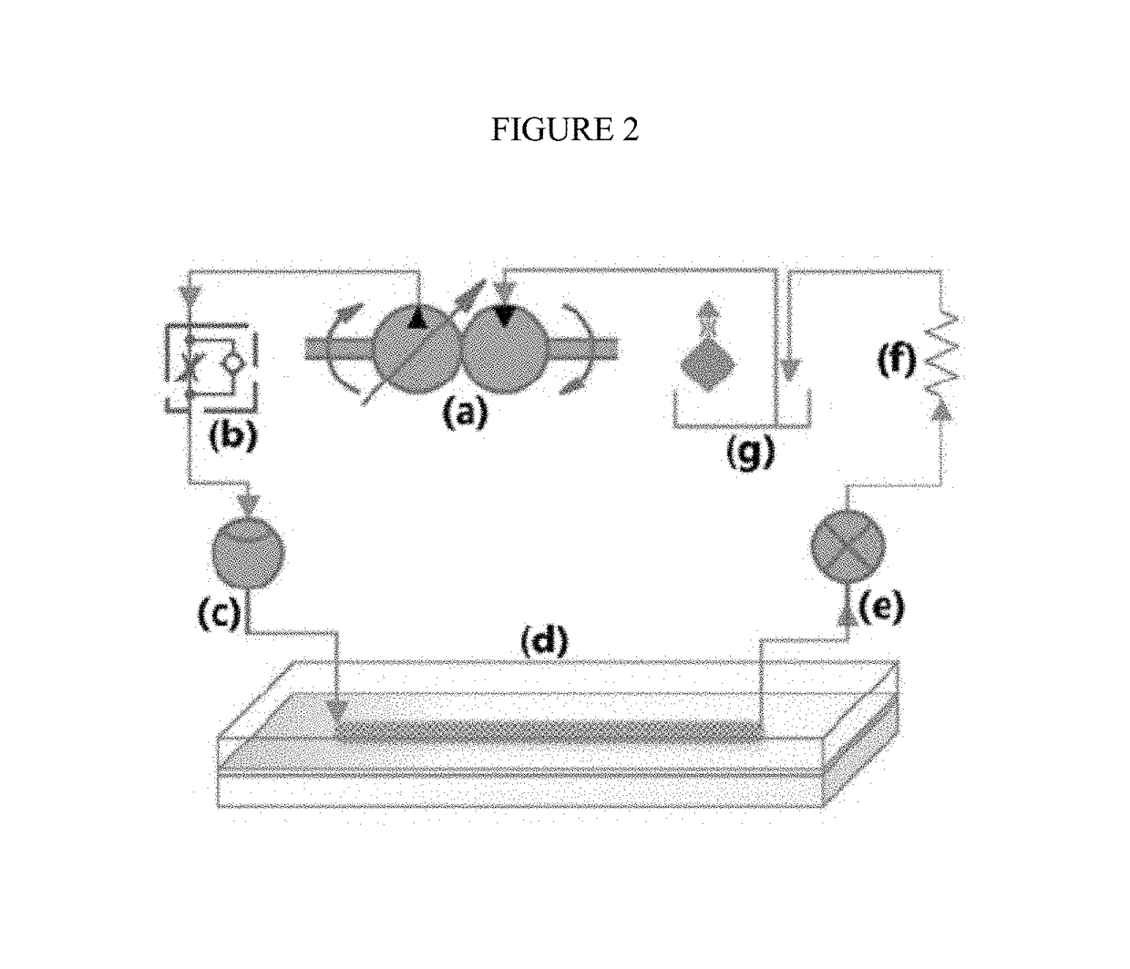
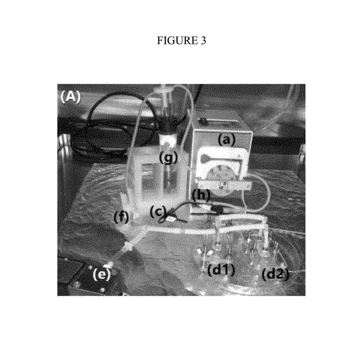
[0011]The present disclosure generally pertains to a biomimetic apparatus configured to simulate physiological conditions. The presently-disclosed apparatus is configured to simulate such physiological conditions by, in part, providing for both barrier and transport interfaces. The presently disclosed apparatus may be used to: test therapeutics for different diseases; study transport; form a substrate for any organ tissue with a barrier and / or transport function; provide a closed loop assembly for fluid flow; mimic underlying and enveloped tissue; and model external environmental conditions.
[0012]As used herein, “analyte” means a specific chemical or biological material or compound that is to be measured.
[0013]As used herein, “biological sample” means biological samples known in the art including, but not limited to, cells, proteins and lipids.
[0014]As used herein, “elastomer” means an elastic polymer including, but not limited to, polydimethylsiloxane and other elastic polymers kno...
PUM
 Abstract
Description
Claims
Application Information