Road vertical contour detection using a stabilized coordinate frame

a coordinate frame and vertical contour technology, applied in the field of driver assistance systems, can solve the problems of cumbersome combination of information from multiple frames at different time steps, different reference planes used at each time step, inaccurate calculation of vertical deviation of the road,

Active Publication Date: 2018-10-30
MOBILEYE VISION TECH LTD
View PDF31 Cites 10 Cited by
  • Summary
  • Abstract
  • Description
  • Claims
  • Application Information

AI Technical Summary

Benefits of technology

[0023]Furthermore, there is a need for systems and methods that account for the effects of radial distortion and rolling shutter in order to accurately detect distances, accurately measure ego-motion, and accurately generate road profiles without artificial upward curvature. In some embodiments, such systems and methods may account for radial distortion and rolling shutter, but may use original images (without adjustments for rolling shutter and radial distortion) for points tracking, in order to avoid computationally expensive pre-warping of images.
[0036]In some embodiments, a computer readable storage medium stores instructions that, when executed by a processor operatively coupled to a driver assistance system mounted in a host vehicle, cause the system to capture, via a camera operatively connectible to the processor, multiple images depicting a portion of a roadway, determine whether a characteristic of the images is attributable to a shadow cast by a tree branch, in accordance with the determination that a characteristic of the image is not attributable to a shadow cast by a tree branch, process the characteristic to determine vertical deviations in the portion of the roadway, and, in accordance with the determination that a characteristic of the image is attributable to a shadow cast by a tree branch, decrease consideration of the characteristic in determining vertical deviations in the portion of the roadway.

Problems solved by technology

One drawback of known methods such as the one described above is that a different reference plane is used at each time step.
By recalculating this ground plane at every step, there may be slight deviations between the reference ground plane in each step, making it cumbersome to combine information from multiple frames at different time steps.
For example, when there are speed bumps in the road, particularly when a speed bump or hump takes up a large portion of one or more frames, then the dominant plane may combine part of the bump and parts of the road, leading to inaccurate calculations of vertical deviations in the road.
Furthermore, small deviations in the road plane can cause new measurements to align poorly.
In theory, the ego-motion and plane information derived from the homography can align the new measurements; however, noise in the plane normal and ego-motion (particularly translation) do not easily allow for accurate alignment.
Another drawback of certain previous methods is their failure to account for both lens distortion (e.g., radial distortion) and the effects of rolling shutter.
If the effects of lens distortion and rolling shutter are ignored, previously known methods may yield qualitatively correct single results with vertical deviations in the road plane identified, but distances may be inaccurate, ego-motion may be inaccurate and there may be a small upward curvature to the resulting profile.

Method used


Image

  • Road vertical contour detection using a stabilized coordinate frame
  • Road vertical contour detection using a stabilized coordinate frame
  • Road vertical contour detection using a stabilized coordinate frame

Examples


Embodiment Construction

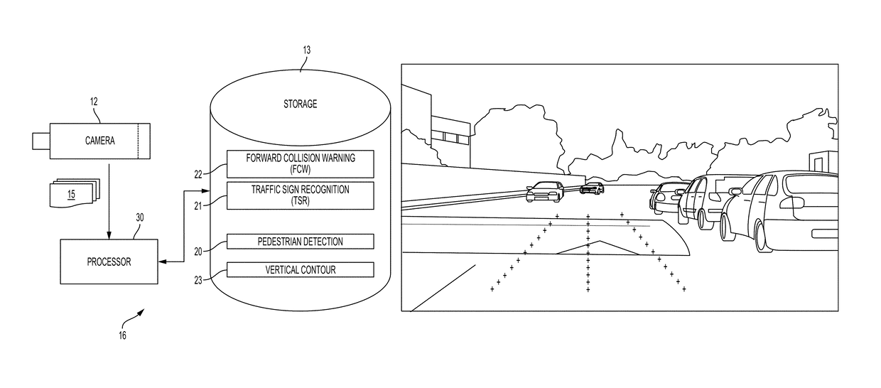
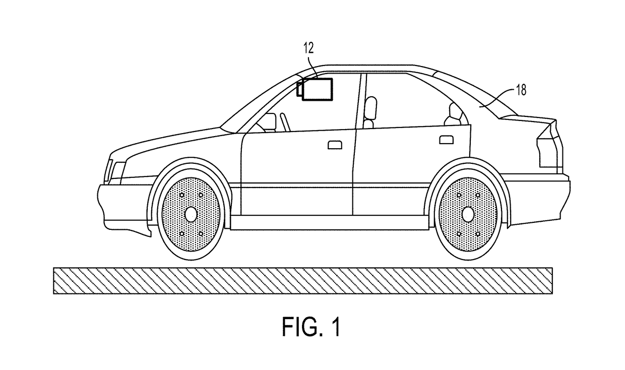
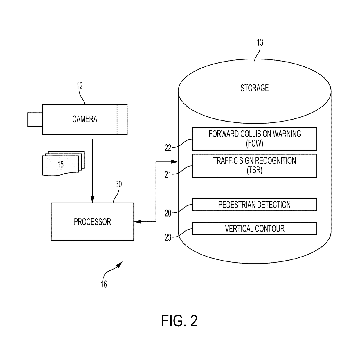
[0061]Reference will now be made in detail to features of the present disclosure, examples of which are illustrated in the accompanying drawings, wherein like reference numerals refer to the like elements throughout. The features are described below to explain the techniques disclosed herein by referring to the figures.

[0062]Before explaining features of the techniques in detail, it is to be understood that the techniques taught herein are not limited in their application to the details of design and the arrangement of the components set forth in the following description or illustrated in the drawings. The techniques taught herein are capable of incorporating other features or of being practiced or carried out in various ways. Also, it is to be understood that the phraseology and terminology employed herein is for the purpose of description and should not be regarded as limiting.

[0063]In this document, lower case coordinates (x,y) are used to denote image coordinates; and upper cas...


PUM


Abstract

In some embodiments, a first homography, created from two images of a roadway, is decomposed to determine an ego-motion, and the ego-motion is used to adjust a previous estimate of a road plane. The adjusted previous estimate of the road plane is combined with the current estimate of the plane to create a second homography, and the second homography is used to determine residual motion and vertical deviation in the surface of the roadway. In some embodiments, multiple road profiles each corresponding to a common portion of a roadway are adjusted in slope and offset by optimizing a function having a data term, a smoothness term and a regularization term; and the adjusted road profiles are combined into a multi-frame road profile. In some embodiments, road profile information for a predetermined number of data points is transmitted in periodic data bursts, with more than one data point per data burst.

Description

CROSS-REFERENCE TO RELATED APPLICATIONS[0001]The present application claims priority from U.S. provisional patent application 62 / 120,929, titled “Road Plane Profile Output in a Stabilized World Coordinate Frame,” filed Feb. 26, 2015; U.S. provisional patent application 62 / 131,374, titled “Road Plane Output in a Stabilized World Coordinate Frame,” filed Mar. 11, 2015; U.S. provisional patent application 62 / 149,699, titled “Road Plane Profile Output in a Stabilized World Coordinate Frame,” filed Apr. 20, 2015; and U.S. provisional patent application 62 / 238,980, titled “Road Plane Output in a Stabilized World Coordinate Frame,” filed Oct. 8, 2015; the disclosures of which are included herein by reference.TECHNICALLY RELATED APPLICATIONS[0002]This application is related to U.S. application Ser. No. 14 / 554,500 (now U.S. Pat. No. 9,256,791), titled “Road Vertical Contour Detection,” filed Nov. 26, 2014; and to U.S. application Ser. No. 14 / 798,575, titled “Road Contour Vertical Detection, ...

Claims


Application Information

Patent Timeline
Patent Type & Authority Patents(United States)
IPC IPC(8): H04N7/18G06T7/13G06T7/73G06T7/60G06T7/40G06T7/20G06T5/00G06K9/52G06K9/46G06K9/00
CPCG06K9/00791G06K9/4604G06K9/52G06T5/006G06T7/13G06T7/40G06T7/60G06T7/74H04N7/18G06T7/20G06T2207/30252G06V20/56G06V20/588
Inventor STEIN, GIDEONBLUMENTHAL, ITAYSHAAG, NADAVKINGSLEY, YAAKOV
Owner MOBILEYE VISION TECH LTD
Why Eureka
Try Eureka