Ultrasonic distance detector

a detector and ultrasonic technology, applied in the field of ultrasonic distance detectors, can solve the problems of difficult detection of accurate distance to liquid level, and achieve the effect of accurately detecting distance, accurate detecting distance, and reducing nois

Active Publication Date: 2020-08-13
DENSO CORP
View PDF0 Cites 0 Cited by
  • Summary
  • Abstract
  • Description
  • Claims
  • Application Information

AI Technical Summary

Benefits of technology

[0005]It is an object of the present disclosure to provide an ultrasonic distance detector that is capable of accurately detecting a distance by reducing a noise superimposed on the signal line.
[0006]In accordance with the disclosure, transmission signals are output from the drive circuit to the two signal lines via the impedance matching circuit, transmission and reception signals on the two signal lines become complementary level signals. Further, when noise signals of the same phase are superimposed on the two signal lines, the transmission and reception signals can be taken in by the receiver circuit with the same phase noise cancelled therefrom. As a result, it is possible to take in the transmission signal and reception signal to accurately detect the distance based on a time difference between the two signals.

Problems solved by technology

In such case, since the signal of the reflected wave detected by the ultrasonic sensor is weak, it may sometimes be difficult to detect an accurate distance to the liquid level due to a noise overriding on the wiring from the ultrasonic sensor to a circuit that receives the signal.

Method used


Image

  • Ultrasonic distance detector
  • Ultrasonic distance detector
  • Ultrasonic distance detector

Examples


first embodiment

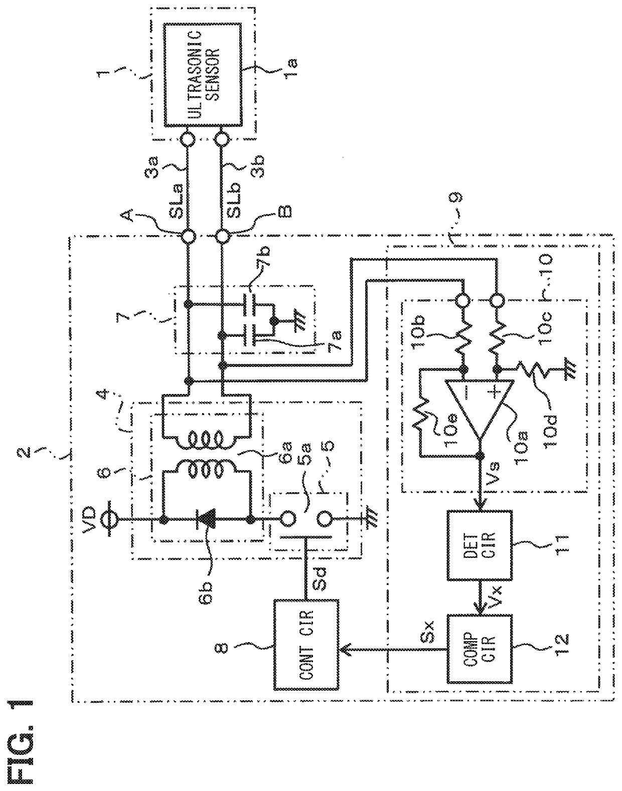
[0011]Hereinafter, the first embodiment of the present disclosure is described with reference to FIGS. 1 and 2. In the present embodiment, as an ultrasonic distance detector using an ultrasonic sensor 1, a liquid level detector 2 provided in a fuel tank of a vehicle is described as an example. A configuration for detecting a liquid level position of the fuel in the fuel tank is that the ultrasonic sensor 1 outputs (e.g., irradiates) an ultrasonic wave from a bottom portion in the fuel tank to the liquid level (i.e., a surface) of the fuel, and the reflected wave is detected by the ultrasonic sensor 1.

[0012]In FIG. 1, the ultrasonic sensor 1 is one having a built-in sensor element 1a formed by laminating, for example, PZT (lead zirconate titanate) having a piezoelectric effect in a round disk shape, and the sensor 1 outputs ultrasonic waves upon having a drive signal applied to both of its terminals. Further, the ultrasonic sensor 1 generates a reception signal by receiving an ultras...

second embodiment

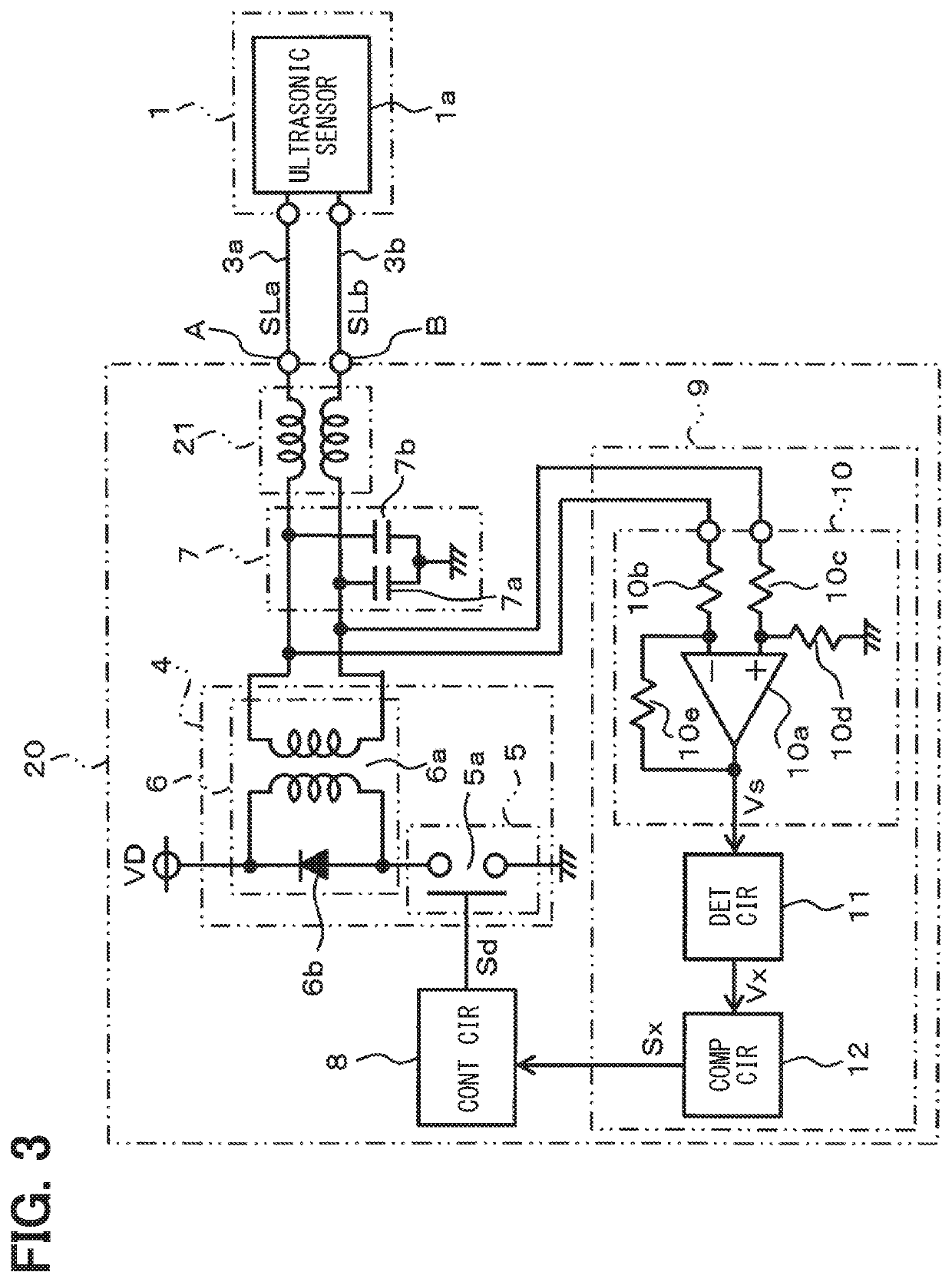
[0035]FIG. 3 shows the second embodiment, about which the differences from the first embodiment is described in the following. In the present embodiment, in addition to the configuration of the first embodiment, a common mode noise filter is additionally provided. That is, as shown in FIG. 3, a liquid level detector 20 is configured to have a common mode choke coil 21 interposed at a position between the impedance matching circuit 6 and the terminals A and B.

[0036]In such manner, the effects of reducing the noise signal Sn superimposed on the two signal lines 3a and 3b are exertable by both of the common mode choke coil 21 and the Y capacitor 7, further enhancing the noise reduction effects, and the signal detection operation can be more accurately performable.

[0037]Therefore, according to the second embodiment, the same effects as that of the first embodiment are achievable, and, in addition, the noise reduction effects can be further enhanced.

[0038]In the second embodiment, the Y ...


PUM


Abstract

A liquid level detector has an ultrasonic sensor connected thereto by two signal lines. When a drive signal is output from a drive circuit, the drive signal is output via an impedance matching circuit, thereby transmission and reception signals on the signal lines flow as complementary level signals. A receiver circuit obtains an amplified signal by amplifying the transmission and reception signals with a differential amplifier circuit, and by cutting a same phase noise signal.

Description

CROSS REFERENCE TO RELATED APPLICATION[0001]The present application is based on and claims the benefit of priority of Japanese Patent Application No. 2019-022646, filed on Feb. 12, 2019, the disclosure of which is incorporated herein by reference.TECHNICAL FIELD[0002]The present disclosure generally relates to an ultrasonic distance detector.BACKGROUND INFORMATION[0003]As an ultrasonic distance detection device, for example, there is an ultrasonic liquid level detection device. In such a device, an ultrasonic sensor utilizing a piezo effect is disposed in a liquid (e.g., a fuel / gasoline), and an ultrasonic wave is output toward a liquid surface, and a reflected wave is received by the same ultrasonic sensor to detect a distance thereto. The liquid level detection device detects an amount of liquid stored inside a tank or the like by obtaining the distance to the liquid level.[0004]In such case, since the signal of the reflected wave detected by the ultrasonic sensor is weak, it may ...

Claims


Application Information

Patent Timeline
Patent Type & Authority Applications(United States)
IPC IPC(8): G01S15/08
CPCG01S15/08
Inventor KOIZUMI, TAKUYAIWAMIYA, HIRONORIKONNO, AKIHIRO
Owner DENSO CORP
Why Eureka
Try Eureka