Magnetic recording head with spin torque oscillator layers satisfying width, thickness and angle relationship formulas

a technology of spin torque oscillator and magnetic recording head, which is applied in the direction of magnetic recording head, data recording, instruments, etc., can solve the problems of inability to record on the magnetic recording medium, the magnetic stability of the magnetic grains drops, and the volume of the magnetic grains decreases, etc., to achieve stable recording properties

Active Publication Date: 2018-11-06
TDK CORPARATION
View PDF9 Cites 111 Cited by
  • Summary
  • Abstract
  • Description
  • Claims
  • Application Information

AI Technical Summary

Benefits of technology

[0009]It is an objective of the present invention to provide a new magnetic recording head, head gimbal assembly and magnetic recording apparatus that can exhibit stable recording properties.
[0017]With the present invention, it is possible to provide a new magnetic recording head, head gimbal assembly and magnetic recording apparatus that can exhibit stable recording properties.

Problems solved by technology

However, when the magnetic grains are made smaller, the problem arises that the thermal stability of the magnetization of the magnetic grains drops accompanying the decline in the volume of the magnetic grains.
Consequently, when the anisotropic magnetic field of the magnetic recording medium exceeds the tolerance determined from the upper limit of this recording magnetic field intensity, recording on the magnetic recording medium becomes impossible.
As a result, even if the assist magnetic field, the intensity of which has been increased, interacts with the recording medium, there is a concern that desired recording properties in the magnetic recording head may not be obtained.

Method used


Image

  • Magnetic recording head with spin torque oscillator layers satisfying width, thickness and angle relationship formulas
  • Magnetic recording head with spin torque oscillator layers satisfying width, thickness and angle relationship formulas
  • Magnetic recording head with spin torque oscillator layers satisfying width, thickness and angle relationship formulas

Examples


Embodiment Construction

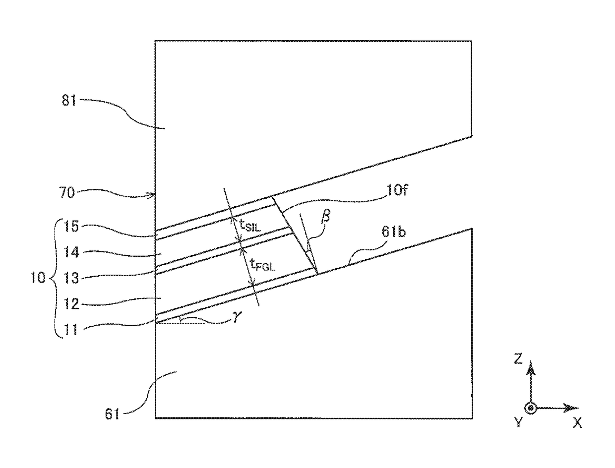
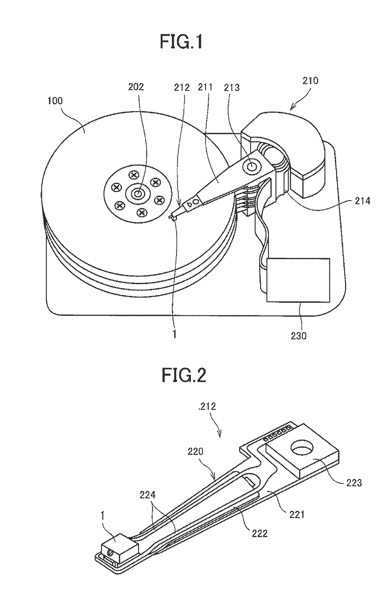
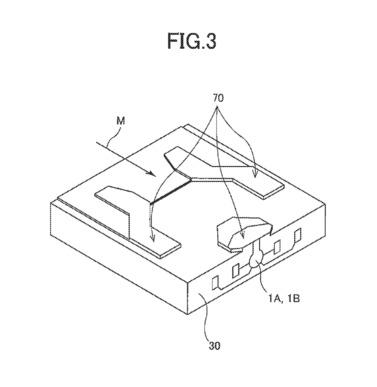
[0032]Before explaining the preferred embodiment of the present invention, terms used in this specification are defined. In the laminated structure or element structure formed in the element formation plane of the slider substrate of the magnetic recording head according to the embodiment, the substrate side is referred to as “downward” and the opposite side is referred to as “upward” when viewed from the layer or element that is the standard. In addition, the air bearing surface side is defined as “forward” and the opposite side is defined as “backward” or “rearward” when viewed from the layer or element that is the standard. Furthermore, in the magnetic recording head according to this embodiment, the X-, Y- and Z-axis directions are defined in some drawings as necessary. Here, the Z-axis direction is the above-described “upward and downward direction”. The +Z side corresponds to the trailing side and the −Z side corresponds to the leading side. In addition, the Y-axis direction i...


PUM

PropertyMeasurementUnit
lengthaaaaaaaaaa
lengthaaaaaaaaaa
thicknessesaaaaaaaaaa

Abstract

A magnetic recording head has a main magnetic pole that generates a recording magnetic field applied on a magnetic recording medium from an end surface that is one portion of an air bearing surface facing the magnetic recording medium; a trailing shield provided on the trailing side of the main magnetic pole with a write gap interposed therebetween; and a spin torque oscillator that is provided in the write gap to be interposed between the main magnetic pole and the trailing shield and that generates a magnetic field that exerts an interaction on the recording magnetic field applied on the magnetic recording medium.

Description

FIELD OF THE INVENTION[0001]The present invention relates to a magnetic recording head, head gimbal assembly and magnetic recording apparatus.BACKGROUND OF THE INVENTION[0002]In the field of magnetic recording using a head and media medium, further improvement in performance of the magnetic recording medium and the magnetic recording head is required along with the increase in the recording density of the magnetic disk device.[0003]The magnetic recording medium is a discontinuous medium in which magnetic grains are gathered, and each magnetic grain has a single domain structure. In this magnetic recording medium, one recording bit is configured by multiple magnetic grains. Consequently, to increase recording density, the magnetic grains must be made smaller, and the unevenness in the boundary between neighboring recording bits must be reduced. However, when the magnetic grains are made smaller, the problem arises that the thermal stability of the magnetization of the magnetic grains...

Claims


Application Information

Patent Timeline
Patent Type & Authority Patents(United States)
IPC IPC(8): G11B5/235G11B5/31G11B5/127G11B5/00
CPCG11B5/1278G11B5/314G11B5/3146G11B5/3116G11B5/235G11B2005/0024G11B5/315
Inventor TAKAHASHI, HIROKAZUTANG, ZHENGYAOROPPONGI, TETSUYAHARA, SHINJI
Owner TDK CORPARATION
Why Eureka
Try Eureka