Passively managed hood and plenum fed air induction system with parallel contaminant management features

a plenum and contaminant management technology, applied in the field of air induction system, can solve the problems of keeping elevated engine compartment air out of the induction, and achieve the effects of reducing peak inlet velocity, reducing inlet air temperature, and increasing engine power

Active Publication Date: 2018-11-13
GM GLOBAL TECH OPERATIONS LLC
View PDF4 Cites 2 Cited by
  • Summary
  • Abstract
  • Description
  • Claims
  • Application Information

AI Technical Summary

Benefits of technology

[0002]Engine air induction systems are designed to provide dry filtered air for combustion with fuel. Generally, engine performance is improved when the induction system delivers the lowest temperature air with the least pressure drop. Air drawn from within the engine compartment is generally at a higher temperature than air drawn from other locations. Vehicle engine compartments have higher air temperatures than their ambient surroundings.SUMMARY
[0003]Factors such as pressure drop through the air induction system, inlet air temperature, noise, and contaminant prevention are considered in achieving an optimal design for an air induction system. Engine cooling fans reject a large amount of elevated temperature air. Engine induction systems draw in air and filter it for engine operation. It is challenging to keep elevated engine compartment air out of the induction. The presently disclosed air induction system substantially increases engine power in comparison with other induction systems by, among other things, reducing inlet air temperature when compared with other induction systems. To do so, the presently disclosed air induction system draws air from two known ambient air sources. One source is in front of the condenser, radiator, and fan module (CRFM), and the second source is through a port in the hood. The air induction system draws the same amount of air from the two ambient air sources. Dual inlet systems reduce peak inlet velocity which helps reduce inlet suction that pulls contaminants into the air induction system. This air induction system improves contaminate ingestion robustness as compared to single inlet designs. Lastly, the dual inlets are ported to the bottom side of a panel filter inside an air box. This layout enables at least one small hole in the lower surface of the air box to drain small amounts of drawn-in water or melted snow without breaching the filtered side of the induction system.
[0008]The air box defines a first inlet port coupled to the hood inlet duct to allow the air to flow from the hood inlet duct into the unfiltered side of the inner box cavity through the first inlet port. The air induction system further includes a seal disposed between the first box inlet port and the hood inlet duct. The first inlet port and the second inlet port may be on opposite ends of the air box to create an even distribution across the panel filter. The hood inlet duct and the air induction plenum assembly facilitate injection of low temperature air into the air box to maximize engine performance. The air induction assembly is disposed in front of the CRFM. The hood inlet duct and the air plenum assembly are sized to provide equal flow into the first inlet port and the second inlet port of the air box. The air induction plenum assembly may include plenums to reduce air inlet velocities to minimize contaminant ingestion. The induction plenum assembly and the hood inlet duct each have a ninety degree relationship between an inlet and an outlet thereof to optimize attenuation. The hood inlet duct and the air induction plenum assembly are sized and located to minimize snow ingestion to passively correct when snow packing occurs in at least one of the hood inlet duct and the air induction plenum assembly. The hood inlet duct and the air induction plenum assembly are sized and located to passively correct an air temperature performance by drawing primary air from a duct with the lowest temperature, wherein the duct is either the hood inlet duct or the air induction plenum assembly. The air induction system passively adjusts a split of the air flow based on vehicle speed and engine cooling fan operation conditions.

Problems solved by technology

It is challenging to keep elevated engine compartment air out of the induction.

Method used


Image

  • Passively managed hood and plenum fed air induction system with parallel contaminant management features
  • Passively managed hood and plenum fed air induction system with parallel contaminant management features
  • Passively managed hood and plenum fed air induction system with parallel contaminant management features

Examples


Embodiment Construction

[0020]While the present disclosures may be described with respect to specific applications or industries, those skilled in the art will recognize the broader applicability of the disclosures. Those having ordinary skill in the art will recognize that terms such as “above,”“below,”“upward,”“downward,” et cetera, are used descriptively of the figures, and do not represent limitations on the scope of the disclosures. Any numerical designations, such as “first” or “second” are illustrative only and are not intended to limit the scope of the disclosures in any way. As used herein, the term substantially denotes variance from exact or perfect values. Skilled artisans recognize that relationships, ratios, or orientations are rarely exact. Therefore, for example, substantially equal may refer to variances of five-percent from exact (one-hundred percent) equality.

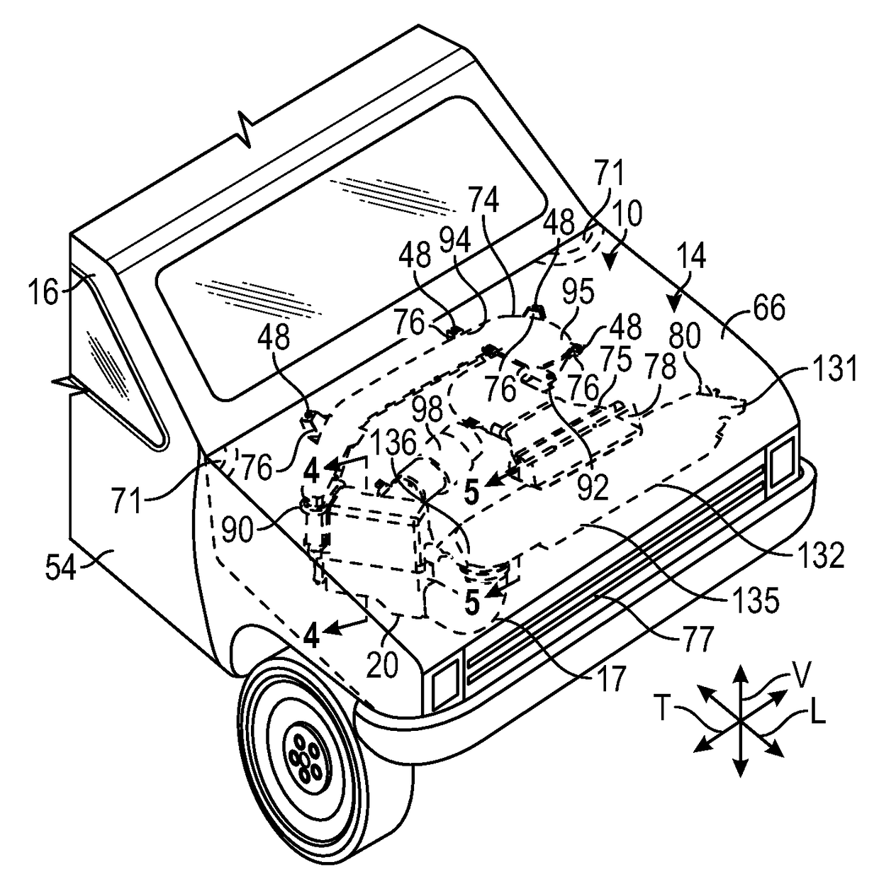
[0021]Referring to the drawings, wherein like reference numbers refer to like components throughout the views, FIG. 1 show a porti...


PUM


Abstract

An air induction system includes a hood inlet duct having a first induction inlet and an air induction plenum assembly having a second induction inlet. The air induction system also includes an air box in fluid communication with the air induction plenum and the hood inlet duct. The air box defines an inner box cavity. The air induction system also includes a panel filter disposed inside the air box, wherein the panel filter divides the inner box cavity so that the first induction inlet and the second induction inlet are upstream of the panel filter.

Description

INTRODUCTION[0001]The present teachings generally relate to an air induction system. Specifically, the present teachings relates to an air induction system with a panel filter and a plenum inlet.[0002]Engine air induction systems are designed to provide dry filtered air for combustion with fuel. Generally, engine performance is improved when the induction system delivers the lowest temperature air with the least pressure drop. Air drawn from within the engine compartment is generally at a higher temperature than air drawn from other locations. Vehicle engine compartments have higher air temperatures than their ambient surroundings.SUMMARY[0003]Factors such as pressure drop through the air induction system, inlet air temperature, noise, and contaminant prevention are considered in achieving an optimal design for an air induction system. Engine cooling fans reject a large amount of elevated temperature air. Engine induction systems draw in air and filter it for engine operation. It is...

Claims


Application Information

Patent Timeline
Patent Type & Authority Patents(United States)
IPC IPC(8): F02M35/10B62D25/12B60K13/06B60K13/02F02M35/08F01P11/02F01P5/02F02M35/024F02M35/16
CPCF02M35/161B60K13/02B60K13/06B62D25/12F01P5/02F02M35/10268F02M35/02416F02M35/02491F02M35/088F02M35/10013F02M35/10052F01P11/02F02M35/0201F02M35/10026F02M35/10157F02M35/10262F02M35/10295F02M35/104B60K11/08
Inventor MACKENZIE, STEVEN K.FARRER, WILLIAM C.HAMILTON, JAMIE L.TURNER, DAVID W.BISHOP, TERRY C.
Owner GM GLOBAL TECH OPERATIONS LLC
Why Eureka
Try Eureka