Organic light emitting element and organic light emitting display device including the same
a technology of light emitting element and display device, which is applied in the direction of solid-state devices, chemistry apparatus and processes, and light-emitting compositions. it can solve the problems of viewing angle and limit the response speed, and achieve the effects of improving the carrier balance, enhancing the efficiency of the organic light emitting element, and increasing the life span
- Summary
- Abstract
- Description
- Claims
- Application Information
AI Technical Summary
Benefits of technology
Problems solved by technology
Method used
Image
Examples
examples 1-1 to 1-17
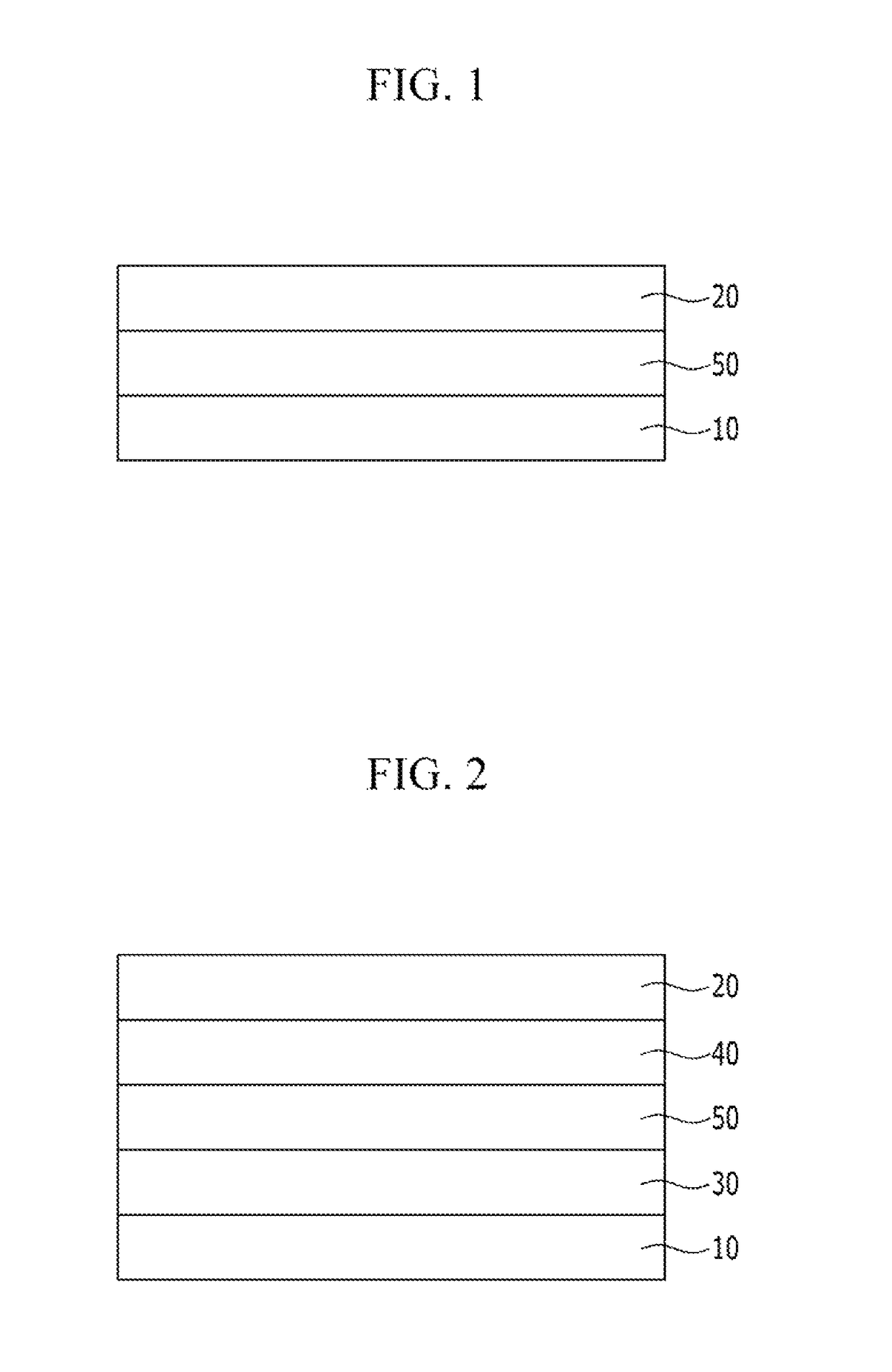
[0184]An indium tin oxide (ITO) transparent electrode was formed with a thickness of 120 nm on a glass substrate. After that, the glass substrate was cleaned using ultrasonic waves, and a pretreatment process (i.e., UV-O3 treatment, heat treatment) was performed.
[0185]A compound represented by Chemical Formula 5 was deposited with a thickness of 50 nm, as a hole injection layer on a pre-treated anode, and then a compound represented by Chemical Formula 6 was deposited with a thickness of 45 nm as a hole transfer layer thereon. Then, a compound of Chemical Formula 4, which is a doping material, was simultaneously deposited at a concentration of 5 wt % to a compound of Chemical Formula 2-1, which is a host material, such that an emission layer having a thickness of 30 nm was formed.
[0186]Next, as an electron transfer layer, a compound of Chemical Formula 1-1 was deposited with a thickness of 25 nm on the emission layer. Then, as a cathode, lithium fluoride was deposited with a thickne...
examples 2-1 to 2-9
and Comparative Examples 4 to 6
[0200]An organic light emitting element was manufactured with the same condition of Example 1, except that lithium quinolate (Liq) was doped to compounds of Chemical Formula 1-1 to Chemical Formula 1-5 in an electron transfer layer. For example, as the electron transfer layer, 50 wt % of Liq was simultaneously deposited as a doping material to the compounds of Chemical Formula 1-1 to Chemical Formula 1-5. Efficiency and life span of the manufactured organic light emitting element are measured under the same conditions described above, and measurement results are shown in Table 2. Additional Examples and Comparative Examples were prepared as described above and shown in Table 2.
[0201]
TABLE 2ExemplaryElectronEfficiencyLifeEmbodimentHosttransfer layer(cd / A)span (h)ExemplaryChemicalChemical4.9120Embodiment 2-1Formula 2-1Formula 1-1:LiqExemplaryChemicalChemical5.1110Embodiment 2-2Formula 2-1Formula 1-2:LiqExemplaryChemicalChemical5.3140Embodiment 2-3Formula...
examples 3-1 to 3-9
and Comparative Examples 10 to 12
[0204]An indium tin oxide (ITO) transparent electrode was formed with a thickness of 120 nm on a glass substrate. After that, the glass substrate was cleaned using ultrasonic waves and a pretreatment process (i.e., UV-O3 treatment, heat treatment) is performed.
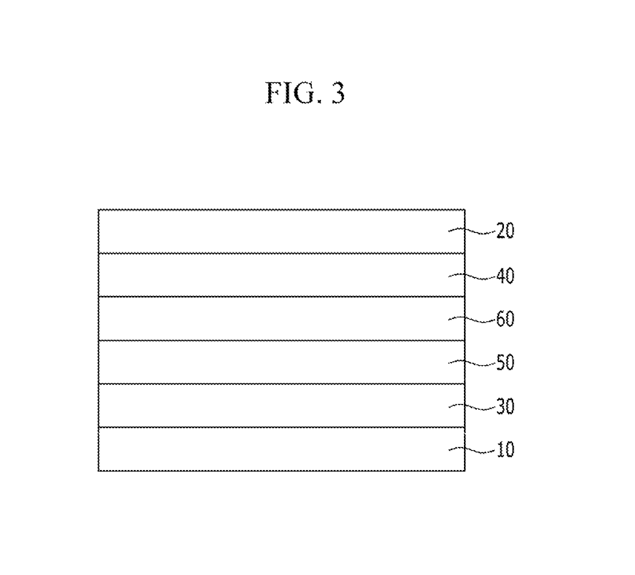
[0205]A compound represented by Chemical Formula 5 was deposited with a thickness of 50 nm, as a hole injection layer on a pre-treated anode, and then a compound represented by Chemical Formula 6 was deposited with a thickness of 45 nm as a hole transfer layer thereon. In addition, (as an anthracene derivative for a host or dopant material), a compound of Chemical Formula 4, which is a doping material, was simultaneously deposited at a concentration of 5 wt % with a compound of Chemical Formula 2-1 such that an emission layer having a thickness of 30 nm was formed.
[0206]After forming the emission layer, a compound of Chemical Formula 1-1 was formed with a thickness of 10 nm, as a hole blocking ...
PUM
| Property | Measurement | Unit |
|---|---|---|
| thickness | aaaaa | aaaaa |
| thickness | aaaaa | aaaaa |
| temperature | aaaaa | aaaaa |
Abstract
Description
Claims
Application Information
 - R&D
- Intellectual Property
- Life Sciences
- Materials
- Tech Scout
- Unparalleled Data Quality
- Higher Quality Content
- 60% Fewer Hallucinations
Browse by: Latest US Patents, China's latest patents, Technical Efficacy Thesaurus, Application Domain, Technology Topic, Popular Technical Reports.
© 2025 PatSnap. All rights reserved.Legal|Privacy policy|Modern Slavery Act Transparency Statement|Sitemap|About US| Contact US: help@patsnap.com


