Power optimization for linear regulator

a technology of power optimization and linear regulators, applied in the direction of lighting apparatus, electrical equipment, light sources, etc., can solve the problem of not increasing the power supply of led strings, etc., and achieve the effect of reducing power consumption, increasing output, and reducing outpu

Active Publication Date: 2018-11-20
DIODES INC
View PDF15 Cites 2 Cited by
  • Summary
  • Abstract
  • Description
  • Claims
  • Application Information

AI Technical Summary

Benefits of technology

[0006]This invention teaches circuits and systems for an LED power supply that provides efficient power supply voltage to the linear regulators. Unlike conventional approaches, a controller monitors the current flow in multiple LED strings and can either lower or raise the LED power supply voltage. If the currents in the LED strings are higher than required, a feedback current is sent to the power supply to decrease its output. If the currents in the LED strings are lower than required, a feedback current is sent to the power supply to increase its output. This capability enables the power supply to respond to operating condition changes that require a higher or lower power supply. Further, the controller can provide real-time control of low dropout voltages at different loading and temperature conditions to lower power consumption and improve the power efficiency.
[0007]For example, a power supply for driving a plurality of LED strings may include a power converter, a multiple-channel linear regulator, and a control circuit. The power converter provides a constant DC output voltage to the LED strings. The multiple-channel linear regulator includes a linear regulator for each LED string, and each linear regulator regulates a current in the LED string in response to a PWM (pulse mode modulation) control signal. The multiple-channel linear regulator also provides an output power status signal. In every PWM switching cycle, the output power status signal is high if the current in any one of the LED strings is above a target current value for that LED string, and the output power status signal is low if the current in all LED strings is below the target current value. The control circuit monitors the output power status signal and provides a feedback signal to the power converter to increase or decrease the DC output voltage accordingly. For example, the controller may monitor the output status signal over a period of time, and increment the feedback signal to cause the power supply to lower its output voltage if the output power status signal is high during any PWM switching cycle in that period of time. If the output power status signal remains low during all PWM switching cycles in the period of time, the feedback signal is decremented to cause the power supply to increase its output voltage. Further, a microcontroller may be used to monitor the output status signal and provide real-time control of low dropout voltages at different loading and temperature conditions to lower power consumption and improve the overall efficiency of the power supply.DEFINITIONS

Problems solved by technology

It cannot increase the power supply to the LED strings when the operating condition changes and requires a higher power supply.

Method used


Image

  • Power optimization for linear regulator
  • Power optimization for linear regulator
  • Power optimization for linear regulator

Examples


Embodiment Construction

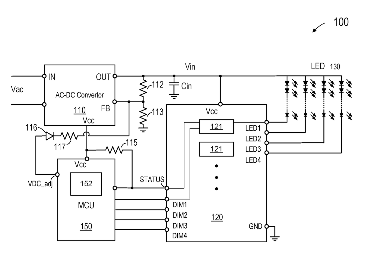
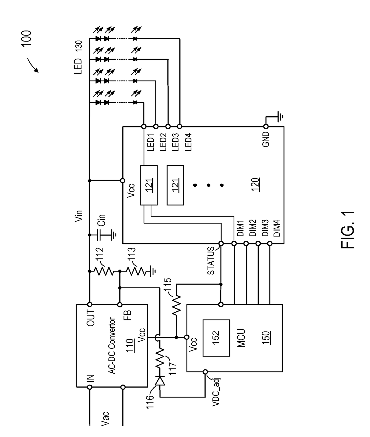
[0028]FIG. 1 is a simplified schematic diagram depicting a power supply for driving an LED (light-emitting-diode) lamp load that embodies certain aspects of this invention. As shown in FIG. 1, power supply 100 includes a power converter 110, e.g., an AC-DC converter, coupled to an AC input source Vac for providing a DC voltage source Vin to an LED load 130 including a plurality of LED strings. Power converter 110 includes a power input node IN coupled to the AC input power source, an output node OUT coupled to a first end of each of the plurality of LED strings, and a feedback node FB for receiving a feedback signal derived from the output node. The power converter converts an AC or DC input voltage at the power input node to an output DC voltage on the output node in response to, in part, the feedback signal. In this embodiment, the feedback signal is derived from the DC output voltage Vin through a voltage divider that includes resistors 112 and 113. For simplicity, in this descri...


PUM


Abstract

A power supply includes a power converter configured to convert an input voltage to a target output DC voltage in response to a feedback signal, the feedback signal having a value. The power supply also includes a regulator coupled to the power converter and configured to generate an output power status signal, which may be in one of two states depending whether an output current from the regulator is above or below a target current over a preset time duration. Further, a control circuit is coupled to the power converter and to the regulator and configured to increment or decrement the value of the feedback signal depending on the state of the power status signal.

Description

CROSS-REFERENCES TO RELATED APPLICATIONS[0001]This application claims priority to U. S. Provisional Patent Application No. 62 / 145,435, filed Apr. 9, 2015, entitled “POWER OPTIMIZATION FOR LINEAR REGULATOR,” commonly owned and incorporated by reference herein. This application is related to U.S. patent application Ser. No. 15 / 049,590 filed Feb. 22, 2016, entitled “ANALOG AND DIGITAL DIMMING CONTROL FOR LED DRIVER”, which claims priority to U.S. Provisional Patent Application No. 62 / 126,440, filed Feb. 27, 2015, entitled “ANALOG AND DIGITAL DIMMING CONTROL FOR LED DRIVER”, commonly owned and incorporated by reference herein.BACKGROUND OF THE INVENTION[0002]Light-emitting diodes (LED) offer many advantages over conventional lighting apparatus, such as long lifetime, high efficiency, and non-toxic materials. With the development of electronic technology, light-emitting diodes are finding ever wider applications. For example, in consumer applications, LED light bulbs are showing promise ...

Claims


Application Information

Patent Timeline
Patent Type & Authority Patents(United States)
IPC IPC(8): H05B33/08H05B44/00
CPCH05B33/0845H05B33/0827H05B33/0815H05B45/46H05B45/10H05B45/37
Inventor WANG, ADRIAN
Owner DIODES INC
Why Eureka
Try Eureka