X-ray collimator size and position adjustment based on pre-shot

a technology of x-ray collimator and pre-shot, which is applied in the field of x-ray equipment, can solve the problems of cumbersome alignment of x-ray source and detector, difficult to determine optimal setting of collimator,

Active Publication Date: 2018-11-27
KONINKLJIJKE PHILIPS NV
View PDF13 Cites 7 Cited by
  • Summary
  • Abstract
  • Description
  • Claims
  • Application Information

AI Technical Summary

Benefits of technology

[0015]According to the invention, a correct setting of the collimator can be determined more accurately. A pre-shot is applied at a small tentative collimator setting, resulting in an exposed field being much smaller than the detector. By determining, for this pre-shot, the cross-section and position on the detector, one can calculate an optimal setting for the collimator to be used during subsequent imaging, based on the known tentative collimator setting.
[0019]In other words the apparatus as proposed herein has a functionality to obtain the field of view correction information using a very small low dosage pre-shot image. This can help to bring down the dosage for both personnel and the patients. This is because it has been observed that medical staff frequently use maximally opened up collimation settings when acquiring X-ray images. The practice of using a collimator setting with maximum aperture provides a good chance that the region of interest is actually captured in the image. However, this comes at the expense of increased dosage. It has been observed that staff is more likely to use maximum collimation in mobile X-ray imagers where the mobile detector is not normally visible during the pre-shot because, for example, the patient lies on same and because the alignment between tube and detector is not known to the required precision because of the portable nature of the detector. It is therefore difficult for the staff to guess a good initial field of view setting for the pre-shot image. The X-ray apparatus with the mobile detector as proposed herein helps take the guess work out of arriving at optimized field of view settings and, in particular, optimized collimator settings.

Problems solved by technology

A particular problem in such apparatus is that it is difficult to determine an optimal setting for the collimator.
Moreover, achieving a proper alignment of the X-ray source and the detector is cumbersome.

Method used


Image

  • X-ray collimator size and position adjustment based on pre-shot
  • X-ray collimator size and position adjustment based on pre-shot
  • X-ray collimator size and position adjustment based on pre-shot

Examples


Embodiment Construction

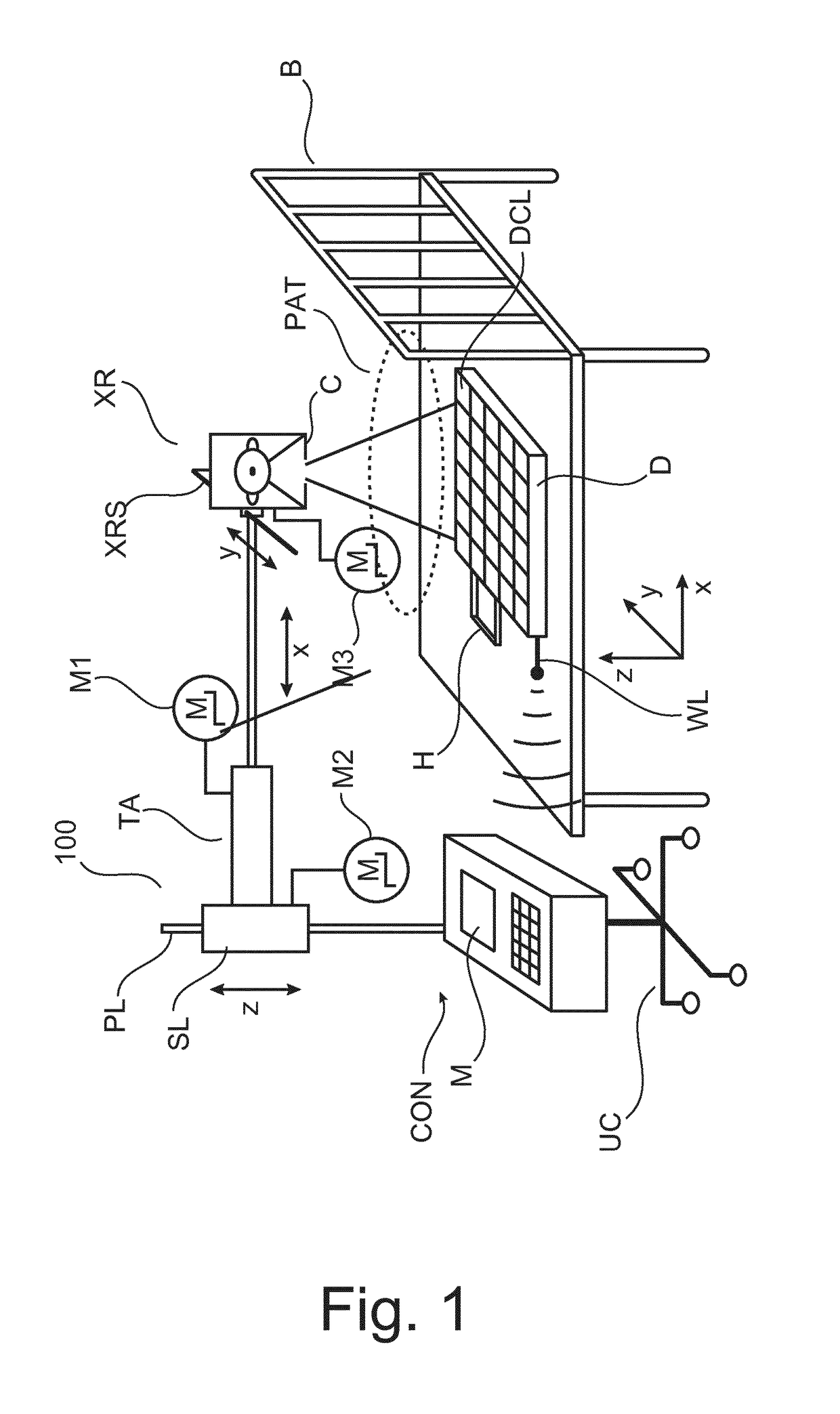
[0037]With reference to FIG. 1 there is shown a mobile X-ray apparatus 100. Mobile X-ray apparatus such as the one shown in FIG. 1 may be used in intensive care wards of in A&E.

[0038]According to one embodiment apparatus 100 is of the “dolly type” and comprises an undercarriage on rollers so as to be position-able at a convenient position relative to the patient PAT. There is an operator console CON for clinical personnel (in the following referred to as operator) for operating imager 100. Operator can control via said console OC image acquisition by releasing individual X-ray exposures for example by actuating a joy stick or pedal or other suitable input means coupled to said console CON.

[0039]The console also includes a display unit M for viewing acquired X-ray images or for displaying a user interface to guide the operator when using the X-ray at the mobile X-ray apparatus 100. In one embodiment the console CON merely comprises the monitor M. According to one embodiment the mobil...


PUM


Abstract

An X-ray apparatus for image acquisition and a related method. The apparatus comprises a field-of-view corrector (CS) configured to receive a scout image (SI) acquired by the imager with a tentative collimator setting in a pre-shot imaging phase where said imager operates with a low dosage radiation cone causing the detector to register the scout image. The low dosage cone has, in the detector's image plane, a first cross section smaller than the total area of the detector surface. The field-of-view corrector (CS) uses said scout image to establish field-of-view correction information for a subsequent imaging phase where the imager is to operate with a high dosage radiation cone, the high dosage higher than the low dosage.

Description

CROSS-REFERENCE TO PRIOR APPLICATIONS[0001]This application is the U.S. National Phase application under 35 U.S.C. § 371 of International Application No. PCT / EP2014 / 052955, filed on Feb. 14, 2014, which claims the benefit of European Patent Application No. 13155428.9, filed on Feb. 15, 2013.These applications are hereby incorporated by reference hereinFIELD OF THE INVENTION[0002]The present invention relates to an X-ray apparatus, to a method of correcting a field of view setting of an X-ray apparatus, to a computer program element and to a computer readable medium.BACKGROUND OF THE INVENTION[0003]Medical personnel in intensive care units or in A & E (Accident and Emergency) departments have come to rely more and more on mobile X-ray imagers. They afford acquisition of X-ray images even under awkward, adverse conditions. For example elderly patients in care homes who have been bed-ridden for long will need to have a chest X-ray taken every day to monitor for possible build-up of wat...

Claims


Application Information

Patent Timeline
Patent Type & Authority Patents(United States)
IPC IPC(8): A61B6/06A61B6/00
CPCA61B6/06A61B6/4085A61B6/4405A61B6/588A61B6/488A61B6/545A61B6/587A61B6/4452
Inventor MAACK, HANNS-INGOKURZE, CHRISTOPHVON BERG, JENSGOOSSEN, ANDRELEVRIER, CLAIREFLORENT, RAOULROOSE, LIESBET HILDE HADEWIJCHMANKE, DIRKHENSEL, MARC
Owner KONINKLJIJKE PHILIPS NV
Why Eureka
Try Eureka