Airfoils for rotor blades of rotary wing aircrafts

a technology for rotor blades and aircraft, which is applied in the direction of machines/engines, liquid fuel engines, transportation and packaging, etc., can solve the problems of restricted maximum lift capacity, comparatively high aerodynamic drag, and provide restricted hover and forward flight performances, so as to improve hover and forward flight performance, reduce aerodynamic drag, and improve maximum lift capacity

Active Publication Date: 2018-11-27
AIRBUS HELICOPTERS DEUT GMBH
View PDF18 Cites 5 Cited by
  • Summary
  • Abstract
  • Description
  • Claims
  • Application Information

AI Technical Summary

Benefits of technology

[0009]It is, therefore, an object of the present invention to provide a new airfoil for a rotor blade of a rotary wing aircraft, said airfoil providing for a reduced aerodynamic drag, an improved maximum lift capacity and improved hover and forward flight performances of said rotor blade. It is a further object of the present invention to provide a new rotor blade having an airfoil that provides for a reduced aerodynamic drag, an improved maximum lift capacity and improved hover and forward flight performances.
[0011]Advantageously, these inventive airfoils exhibit a reduced aerodynamic drag by means of extended laminarity. Furthermore, an underlying maximum lift capacity is improved. Moreover, more negative, i. e. nose-down, static pitching moments around the quarter-chord of the airfoils due to the applied modifications to the camber line are acceptable, since dynamic loads as seen in numerical simulations and wind tunnel measurements prove to remain within those of prior art airfoils.
[0012]More specifically, the inventive airfoils exhibit reduced aerodynamic drag compared to prior art airfoils due to extended laminar running lengths on the upper side, i. e. the extrados. This is achieved by an improved leading edge geometry and by introducing a well-defined main pressure recovery at a downstream position, i. e. towards the trailing edge of the airfoil. These measures further enable the reduction of suction peaks and thereby allow for higher maximum lift coefficients at moderate Mach numbers as well as the reduction of transonic shocks at high lift coefficients. Furthermore, the application of the inventive airfoils provides for improved hover and forward flight performances of a given rotor of a rotary wing aircraft.
[0036]Thus, new rotor blades and in particular new main rotor blades can be manufactured that allow for an improvement of an overall performance of a main rotor of a rotary wing aircraft, in particular of a helicopter, while maintaining favorable unsteady characteristics thereof, such as dynamic stall. Advantageously, such new main rotor blades can be provided with a particular geometric shape by application of the inventive airfoils at specific radial positions along these main rotor blades.

Problems solved by technology

However, these airfoils only provide for a restricted maximum lift capacity and a comparatively high aerodynamic drag.
Furthermore, they only provide for restricted hover and forward flight performances.

Method used


Image

  • Airfoils for rotor blades of rotary wing aircrafts
  • Airfoils for rotor blades of rotary wing aircrafts
  • Airfoils for rotor blades of rotary wing aircrafts

Examples


Embodiment Construction

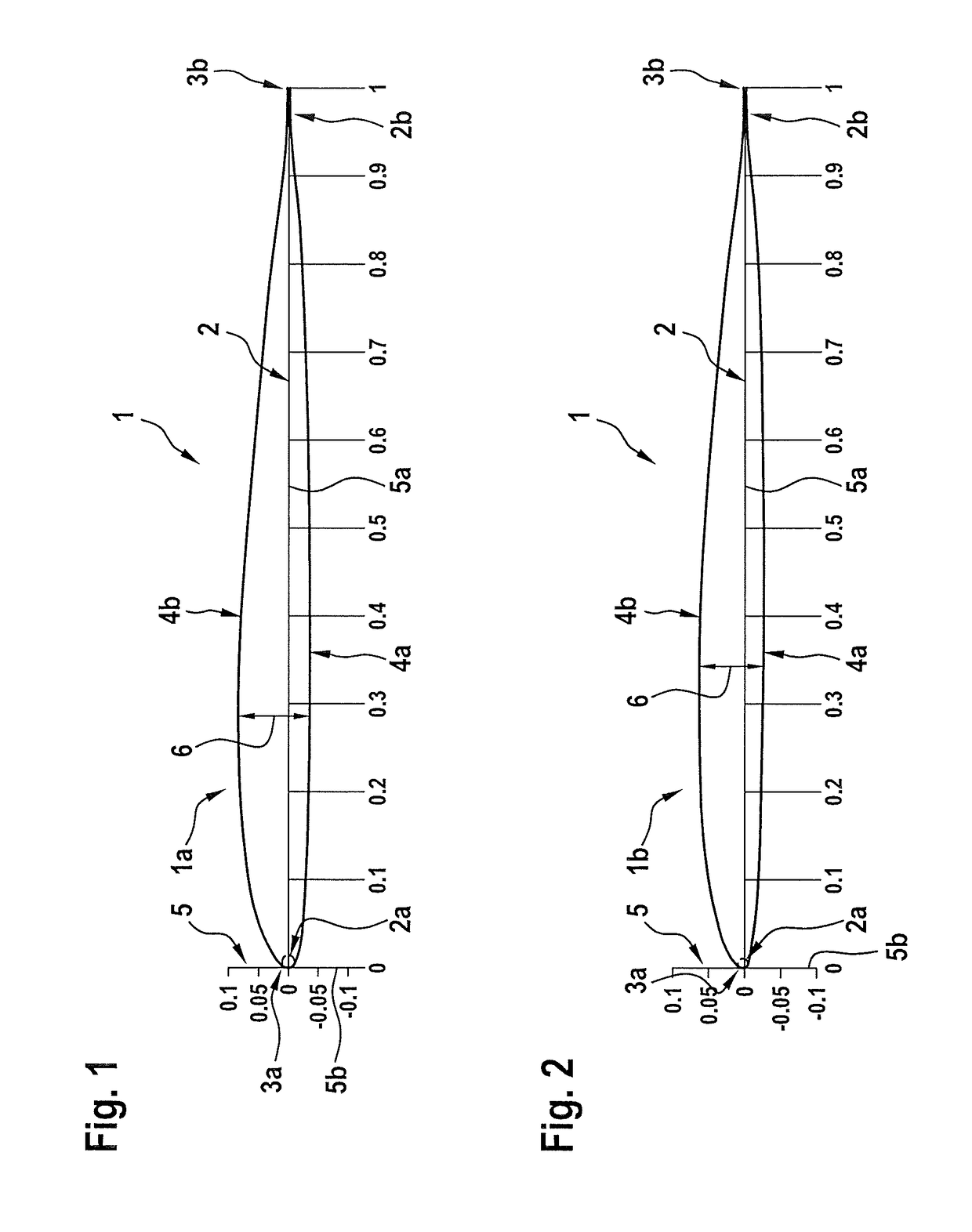
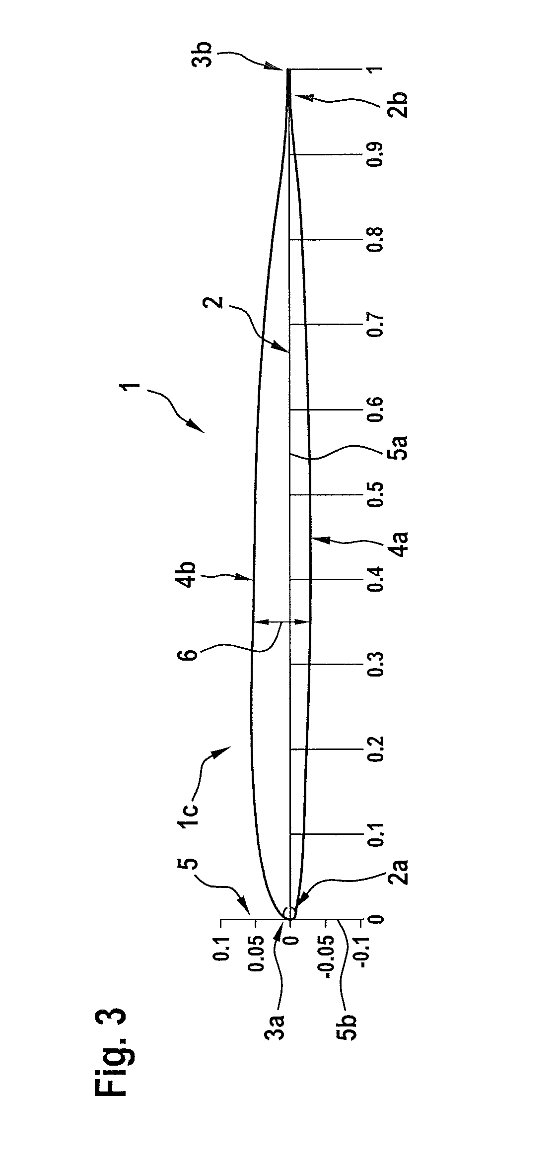
[0045]FIG. 1 shows a rotor blade 1 of a rotary wing aircraft that is provided with an airfoil 1a according to a first aspect of the present invention. The airfoil 1a preferably comprises a maximum thickness to chord ratio of 12%.

[0046]Illustratively, the airfoil 1a comprises a leading edge 3a and a trailing edge 3b, which are illustratively arranged on an airfoil chord line 2 of the airfoil 1a. The airfoil 1a illustratively further comprises an intrados 4a and an extrados 4b that extend between the leading edge 3a and the trailing edge 3b. The intrados 4a is defined by predetermined intrados coordinate value pairs x / c, yint / c and the extrados 4b is defined by predetermined extrados coordinate value pairs x / c, yext / c. Therein, x is a distance from the leading edge 3a to the trailing edge 3b along the chord line 2, c is a length of the airfoil 1a in chord direction, yint is a distance between the chord line 2 and a respective intrados surface and yext is a distance between the chord l...


PUM


Abstract

An airfoil for a rotor blade of a rotary wing aircraft, the airfoil having a predetermined maximum thickness to chord ratio and comprising, between a leading edge and a trailing edge, an extrados and an intrados, the intrados being defined by predetermined intrados coordinate value pairs and the extrados being defined by predetermined extrados coordinate value pairs, wherein a maximum error of each one of the predetermined intrados coordinate value pairs and the predetermined extrados coordinate value pairs amounts to ±3%.

Description

CROSS REFERENCE TO RELATED APPLICATION[0001]This application claims priority to European patent application No. EP 15400028.5, filed Jul. 3, 2015, the disclosure of which is incorporated in its entirety by reference herein.BACKGROUND OF THE INVENTION[0002](1) Field of the Invention[0003]The invention is related to an airfoil for a rotor blade of a rotary wing aircraft, said airfoil having a predetermined maximum thickness to chord ratio. The invention is further related to a rotor blade of a rotary wing aircraft.[0004](2) Description of Related Art[0005]Airfoils for rotor blades of rotary wing aircrafts are generally characterized by an extrados and an intrados that are arranged between corresponding leading and trailing edges of the airfoils and that are defined by predetermined intrados coordinate value pairs x / c, yint / c and predetermined extrados coordinate value pairs x / c, yext / c. Therein, x is a distance from a leading edge to a trailing edge along a chord line of the airfoil, ...

Claims


Application Information

Patent Timeline
Patent Type & Authority Patents(United States)
IPC IPC(8): B64C3/14F04D29/38F04D29/18B64C27/467
CPCB64C3/14F04D29/384F04D29/181B64C27/467Y02T50/30Y02T50/60
Inventor KLEIN, ALEXANDERGUDE, JONASLUTZ, THORSTENROHARDT, CLAAS-HINRIKRICHTER, KAI
Owner AIRBUS HELICOPTERS DEUT GMBH
Why Eureka
Try Eureka