Process for producing a turbine rotor

Active Publication Date: 2018-11-27
BORG WARNER INC
11 Cites 0 Cited by

AI-Extracted Technical Summary

Problems solved by technology

However, this known process has the disadva...

Benefits of technology

[0005]According to the invention, it is possible to achieve a defined diffusion zone in the turbine wheel and on the shaft (steel shaft) when connecting the turbine wheel an...

Abstract

A process for producing a turbine rotor (1), which has, as joining partners, a turbine wheel (2) made of TiAl and a shaft (3) produced from steel, with the following process steps: providing the turbine wheel (2); providing a solder; providing the shaft (3); and connecting the turbine wheel (2) and the shaft (3) by electron beam soldering by means of an electron beam (5).

Application Domain

Blade accessoriesSoldering apparatus +2

Technology Topic

SolderingAerospace engineering +3

Image

  • Process for producing a turbine rotor

Examples

  • Experimental program(1)

Example

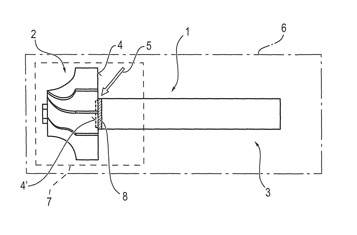
[0011]As the FIGURE shows, the turbine wheel 2 is connected to a shaft, preferably a steel shaft, e.g. made of construction steel or a martensitic steel. For this purpose, the turbine rotor 1 has a connection device 8, which is in the form of an electron beam solder joint. The connection device 8 can additionally be provided with a selectable joint geometry, e.g. with a journal on a joining partner and, on the other joining partner, a recess for the insertion of the journal.
[0012]The solder joint 8 is in this case arranged between the back side 4 of the turbine wheel 2 and an end face 4′ of the shaft 3, as is apparent in detail from the illustration in the FIGURE.
[0013]For illustrating the process according to the invention for producing the turbine rotor 1, an electron beam soldering machine 6 is shown by a dot-dashed line, having a process chamber 7 in vacuo. It is therefore possible to carry out the electron beam soldering process symbolized by the arrow 5 in vacuo, in which case the EB beam 5 can be divided in such a way that it alternately moves over the respective temperature windows of the joining partners 2, 3.
[0014]As mentioned in the introduction, the joining partners formed by the turbine wheel 2 and the shaft 3 are subjected to defined uniform turning during the soldering operation.
[0015]In addition to the above written disclosure of the invention, reference is hereby explicitly made to the drawing, to supplement said written disclosure.
LIST OF REFERENCE SIGNS
[0016] 1 Turbine rotor [0017] 2 Turbine wheel [0018] 3 Shaft [0019] 4 Back of the turbine wheel [0020] 4′ End face of the shaft 3 [0021] 5 EB beam [0022] 6 EB machine [0023] 7 Vacuum chamber [0024] 8 Connection device (solder joint)

PUM

no PUM

Description & Claims & Application Information

We can also present the details of the Description, Claims and Application information to help users get a comprehensive understanding of the technical details of the patent, such as background art, summary of invention, brief description of drawings, description of embodiments, and other original content. On the other hand, users can also determine the specific scope of protection of the technology through the list of claims; as well as understand the changes in the life cycle of the technology with the presentation of the patent timeline. Login to view more.
Why Eureka
Try Eureka