Bias circuit for supplying a bias current to a RF power amplifier

a bias current and power amplifier technology, applied in the direction of electric pulse generator circuit, amplifier modification to reduce non-linear distortion, vacuum tube pulse generation, etc., can solve problems such as degrading the performance of rf power amplifiers

Active Publication Date: 2018-11-27
RAFAEL MICROELECTRONICS INC
View PDF2 Cites 4 Cited by
  • Summary
  • Abstract
  • Description
  • Claims
  • Application Information

AI Technical Summary

Benefits of technology

[0004]The present invention discloses a bias circuit for supplying a bias current to a RF power amplifier by using multiple voltage reference circuits coupled between the base terminal of a bipolar transistor and a voltage supply for generating a bias current to the RF power amplifier, wherein each of the multiple voltage reference circuits respectively clamps to a reference voltage at a node coupled to a conductive path having a current flowing from the voltage supply to the base terminal of the bipolar transistor, wherein when the current flowing out of the voltage supply increases, the current flowing through each of the multiple voltage reference circuits will also increases so that the variation range of the current flowing into the base terminal of the bipolar transistor will be kept in a smaller range compared with the variation range of the current flowing out of the power supply, thereby increasing the linearity of the RF power amplifier.

Problems solved by technology

However, as the power provided by the battery varies from time to time, the bias current supplied to the RF power amplifier will also varies in a large range and hence degrade the performance of the RF power amplifier.

Method used


Image

  • Bias circuit for supplying a bias current to a RF power amplifier
  • Bias circuit for supplying a bias current to a RF power amplifier
  • Bias circuit for supplying a bias current to a RF power amplifier

Examples


Embodiment Construction

[0027]The detailed explanation of the present invention is described as following. The described preferred embodiments are presented for purposes of illustrations and description, and they are not intended to limit the scope of the present invention.

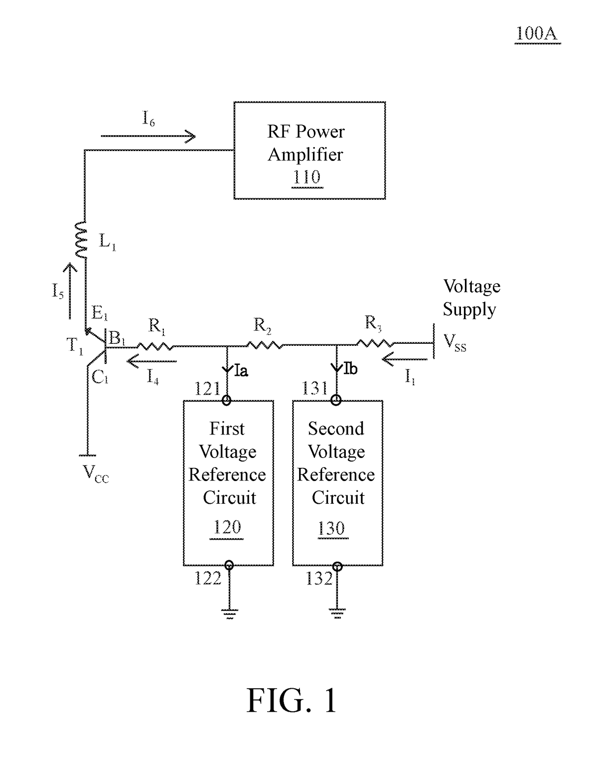
[0028]FIG. 1 illustrates a bias circuit 100A for supplying a bias current I6 to a RF power amplifier 110 in accordance with one embodiment of the present invention. The bias circuit 100A comprises a first bipolar transistor T1 (e.g., GaAs bipolar transistor), a first voltage reference circuit 120 and a second voltage reference circuit 130. The first bipolar transistor T1 has a base terminal B1, a collector terminal C1 and an emitter terminal E1. The emitter terminal E1 of the first bipolar transistor T1 is electrically coupled to the RF power amplifier 110 (e.g., through an inductive component L1) for supplying a bias current I6 to the RF power amplifier 110. A voltage supply Vcc is electrically coupled to the collector terminal C1 of th...


PUM


Abstract

A bias circuit for supplying a bias current to a RF power amplifier by using at least two voltage reference circuits coupled between the base terminal of a bipolar transistor and a voltage supply for generating a bias current to the RF power amplifier, wherein each of the at least two voltage reference circuits respectively clamps to a reference voltage at a corresponding terminal node of the voltage reference circuit on a conductive path having a current flowing from the voltage supply to the base terminal of the bipolar transistor, wherein when the current flowing out of the voltage supply increases, the current flowing through each of the at least two voltage reference circuits will also increases, so that the variation range of the bias current to the RF power amplifier will be kept in a smaller range compared with the variation range of the current flowing out of the power supply, thereby increasing the linearity of the RF power amplifier.

Description

BACKGROUND OF THE INVENTION1. Field of the Invention[0001]The invention relates to RF power amplifier and, in particular, but not exclusively, to a bias circuit for supplying a bias current to a RF power amplifier.2. Description of the Prior Art[0002]A stable bias current supplied to a RF power amplifier is one of the most important factors for determining the performance of a RF power amplifier, especially for a RF power amplifier requires high-linearity. Nowadays, a wireless communication, such as WCDMA, LTE or WIFI, need a RF power amplifier with high-linearity. The RF power amplifier with high-linearity plays a very import role or even becomes a must in the future mobile communication, especially the fifth generation mobile communication.[0003]A voltage supply of a RF power amplifier circuit in a mobile device is provided by a battery. However, as the power provided by the battery varies from time to time, the bias current supplied to the RF power amplifier will also varies in a...

Claims


Application Information

Patent Timeline
Patent Type & Authority Patents(United States)
IPC IPC(8): H03K3/04H03F3/20H03F3/189H03F1/32H04M1/02
CPCH03F1/32H03F3/189H03F3/20H03F2200/451H04M1/0202H03F1/302H03F3/19H03F3/21H03F1/30H03F3/245
Inventor WU, CHIH-WEN
Owner RAFAEL MICROELECTRONICS INC
Why Eureka
Try Eureka