High-efficiency gradient hierarchy complex desulfurizing tower

a desulfurizing tower and gradient hierarchy technology, applied in the direction of dispersed particle separation, separation process, chemistry apparatus and processes, etc., can solve the problems of high-performance desulfurization requirements of wet desulfurizing devices, no operation has yet appeared, and no precedent for using wet desulfurizing devices that can reach the emission requirements of gas-fired units, etc., to achieve excellent desulfurization efficiency and dedusting performance, increase mass transfer area, and limited footprint area

Active Publication Date: 2018-12-04
HUANENG POWER INT INC +1
View PDF12 Cites 5 Cited by
  • Summary
  • Abstract
  • Description
  • Claims
  • Application Information

AI Technical Summary

Benefits of technology

[0041]The present disclosure has the following advantageous effects: gradient hierarchy complex desulfurization techniques are utilized in the desulfurizing tower, which has excellent desulfurization efficiency and dedusting performance, and the desulfurization efficiency is 99% or more, preferably over 99.5%, and the dedusting efficiency is 90% or more, and the desulfurizing tower is suitable for treating medium high sulfur coal and high sulfur coal flue gases, especially for treating high sulfur coal flue gases; at the same time, since the desulfurizing tower is a single tower, it is especially suitable for modifying existing desulfurizing devices with narrow spaces and limited footprint areas.
[0042]In particular, when the unique S-type gas liquid mass transfer mechanism of the present disclosure is in operation, the limestone slurry with a high pH value is distributed to the tray by a slurry pipeline that is above the tray and from the outside of the tower, the slurry flows into the U-shaped collecting slot along the parallel direction of the plates, the slurry in the U-shaped collecting slot then flows to the outside of the tower by the slurry pipeline to form a cycle while the slurry forms a layer of limestone slurry film on the tray; the flue gases enter through the gas inlets, and due to the gas sealing plates provided at both sides of the gas inlets, the flue gases can only enter the intermediate channels, and then enter the slurry film on the tray through the bottom clearances of the gas outlets. The flue gases mix thoroughly with the slurry, form the froth regime or the steady spray regime and interact with the slurry, which increases mass transfer area, improves mass transfer effects while preventing slurry particles from deposition, and gases and liquids contact thoroughly under high pH conditions, and the desulfurization efficiency is significantly improved.
[0043]At the same time, by providing the U-shaped collecting slot with the oxidation air tube, in one aspect the oxidation air may oxidize sulfites in the U-shaped collecting slot, and prevent the formation of hard scale of sulfates and soft scale of sulfites, in another aspect, the oxidation air may stir the slurry and prevent the formation of deposited fouling. The present disclosure efficiently improves the desulfurization and dedusting performance.

Problems solved by technology

However, so far cases in which ultra-low emission techniques suitable for medium high sulfur coal and high sulfur coal (Sar>1.5%) are in successful commission and operation have not yet appeared.
In China, there are successful operational cases with desulfurization efficiency of 98%, but for units burning high sulfur coal, no precedent for using wet desulfurizing devices that can reach the emission requirements of gas-fired units exists.
However, there is no such high performance desulfurization requirement for wet desulfurizing devices in other countries because the total amount of coal-fired units is not large (compared to that in China).
There are two main reasons why desulfurization efficiency of conventional limestone-gypsum desulfurizing devices is restricted: 1) restricted by conditions such as oxidation and crystallization of gypsum, dissolution of limestone, and consumption control, and the like, generally the pH value of the absorption slurry is 5.2 to 5.8, which restricts the activity of absorbents; 2) restricted by the single tower, total flow rate of the absorption slurry cannot be too high, otherwise it may cause an overcapacity of the liquid in the tower and lead to abrupt increase in the pressure drop of the flue gases, so that operation is impossible.
To some extent, the techniques of series-connected towers achieve ultra-high desulfurization efficiency of medium high sulfur coal and high sulfur coal, and resolve the issue of emission compliance, but the techniques of series-connected towers have multiple disadvantages: 1) initial investment of the project is high; 2) since there are primary and secondary absorption towers, footprint area is large, and modification of the existing devices cannot be realized for a lot of projects; 3) the number of devices is relatively large, the device failure rate and the repair and maintenance effort are high, and the operating costs are also high.
There are certain limitations in such technique if it is directly applied to limestone-gypsum wet desulfurization under high gas velocity, suspension slurry medium and variable load operating conditions.
However, current flue gas desulfurization techniques generally use empty tower dual-flow spray techniques, which has the following problems: in one aspect, spray slurry falls directly into the slurry pond at the bottom of the tower, and cannot be collected or absorbed segmentally, and the pH value of the slurry is without gradient, so that desulfurization efficiency cannot be further improved when the reaction is near its equilibrium point; in another aspect, the dedusting efficiency of spray washing is very low for fine dust in the flue gases, especially for fine dust of PM2.5 or less, in addition, high velocity flue gases may take away fine droplets ejected from spray nozzles, so that gypsum contained in these droplets also increase the emission concentration of dust.

Method used


Image

  • High-efficiency gradient hierarchy complex desulfurizing tower
  • High-efficiency gradient hierarchy complex desulfurizing tower
  • High-efficiency gradient hierarchy complex desulfurizing tower

Examples


Embodiment Construction

[0060]To make the object, technical solutions, and advantages of the present disclosure more clear, the present disclosure will be further described in detail below with reference to the drawings and embodiments. It should be understood that the specific embodiments described herein are for illustration purpose only, and are not intended to limit the present disclosure.

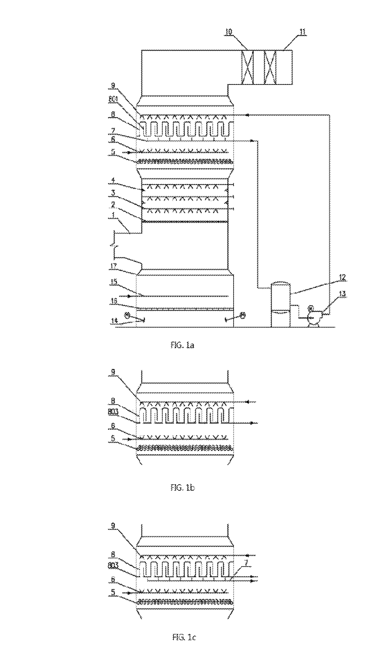
[0061]In an preferable embodiment of the present disclosure, as shown in FIG. 1a, a high-efficiency gradient hierarchy complex desulfurizing tower comprises a tower body 17, a gas import 1 is provided in the middle of the tower body 17, a gas discharge port 11 is provided at the top of the tower body 17, and the tower body 17 comprises an oxidization and crystallization stage, a coarse desulfurization and dedusting stage, a fine desulfurization and dedusting stage, and a horizontal demisting stage from the bottom up; wherein,

[0062]The oxidization and crystallization stage comprises a slurry pond provided at the bottom...


PUM

PropertyMeasurementUnit
heightaaaaaaaaaa
velocityaaaaaaaaaa
velocityaaaaaaaaaa

Abstract

A high-efficiency gradient hierarchy complex desulfurizing tower includes a tower body. The tower body tower includes an oxidization and crystallization stage, a coarse desulfurization and dedusting stage, a fine desulfurization and dedusting stage, and a horizontal demisting stage from the bottom up. The oxidization and crystallization stage tower includes a pond and a separation mechanism provided in the pond and separating the pond into an upper area and a lower area. The coarse desulfurization and dedusting stage tower includes a gas distributing board and a multi-layer spray layer that are placed above a gas import, the spray layer being in connection with the pond. The fine desulfurization and dedusting stage tower includes a tube demister, a flushing layer, a film liquid holdup layer, a liquid holdup layer recycling can, the pH of slurry in the liquid holdup layer recycling can being higher than the pH of slurry in the pond.

Description

[0001]The present disclosure claims the benefit of priorities of Chinese Patent Application Nos. CN201520530484.0 and CN201520778413.2.TECHNICAL FIELD[0002]The present disclosure relates to a desulfurizing tower, especially a high-efficiency gradient hierarchy complex desulfurizing tower.RELATED ART[0003]In recent years, coal-fired power plants in China eager to cope with China's environmental threshold value pressure generally use medium low sulfur coal, which is high in price, but low in sulfur content and ash, and high in calorific value. Ultra-low emission techniques suitable for medium low sulfur coal (Sar<1.5%) have been in commission and operation successfully. However, so far cases in which ultra-low emission techniques suitable for medium high sulfur coal and high sulfur coal (Sar>1.5%) are in successful commission and operation have not yet appeared.[0004]However, approximately 30% coals of China's coal resources have a sulfur content of 2% or more, and in particular...

Claims


Application Information

Patent Timeline
Patent Type & Authority Patents(United States)
IPC IPC(8): B01D47/00B01D47/12B01D53/50B01D53/80B01D45/12
CPCB01D53/50B01D53/504B01D53/80B01D47/12B01D2251/404B01D2251/606B01D2258/0283B01D45/12B01D47/021B01D47/06
Inventor LI, WEIDONGZHAO, HONGHAN, CHANGMINHE, YONGZHANG, YI
Owner HUANENG POWER INT INC
Why Eureka
Try Eureka