
Launch pad flame deflector structure and method of making the same

a technology of flame deflector and launch pad, which is applied in the direction of coating, coating, metallic material coating process, etc., can solve the problems of not showing no changes, and structures produced in this manner that cannot exhibit uniform high resistance to rocket flames

Inactive Publication Date: 2018-12-11
RENZI FAMILY TRUST
View PDF5 Cites 0 Cited by
  • Summary
  • Abstract
  • Description
  • Claims
  • Application Information

AI Technical Summary

Benefits of technology

The technical effect of this patent is to provide a reliable flame deflector surface that can be manufactured uniformly and secured together to produce a durable surface. This results in a minimization of spalling of the refractory during a launch event and minimizes the risk of damage to the ascending rocket, gantry, or nearby ground facilities. This reduces launch-related damage and avoids repair costs and down-time that would delay subsequent launch efforts.

Problems solved by technology

However, to the best of my knowledge, no changes have been made since 2009 by the KSC to its list of approved refractory materials.
This FondueFyre cement has generally been applied to the metal base by spraying, on location, in a manner analogous to construction of a swimming pool, known colloquially as “guniting.” Experience has shown that the structures produced in this manner fail to exhibit uniformly high resistance to rocket flames, and often need to undergo expensive repairs after a launch.
Further, the refractory surface is also vulnerable to tropical rains, salt deposition, and other adverse environmental influences.
A series of NASA reports detail various attempts at a solution, with less-than optimal results.

Method used


Image

  • Launch pad flame deflector structure and method of making the same
  • Launch pad flame deflector structure and method of making the same
  • Launch pad flame deflector structure and method of making the same

Examples


Embodiment Construction

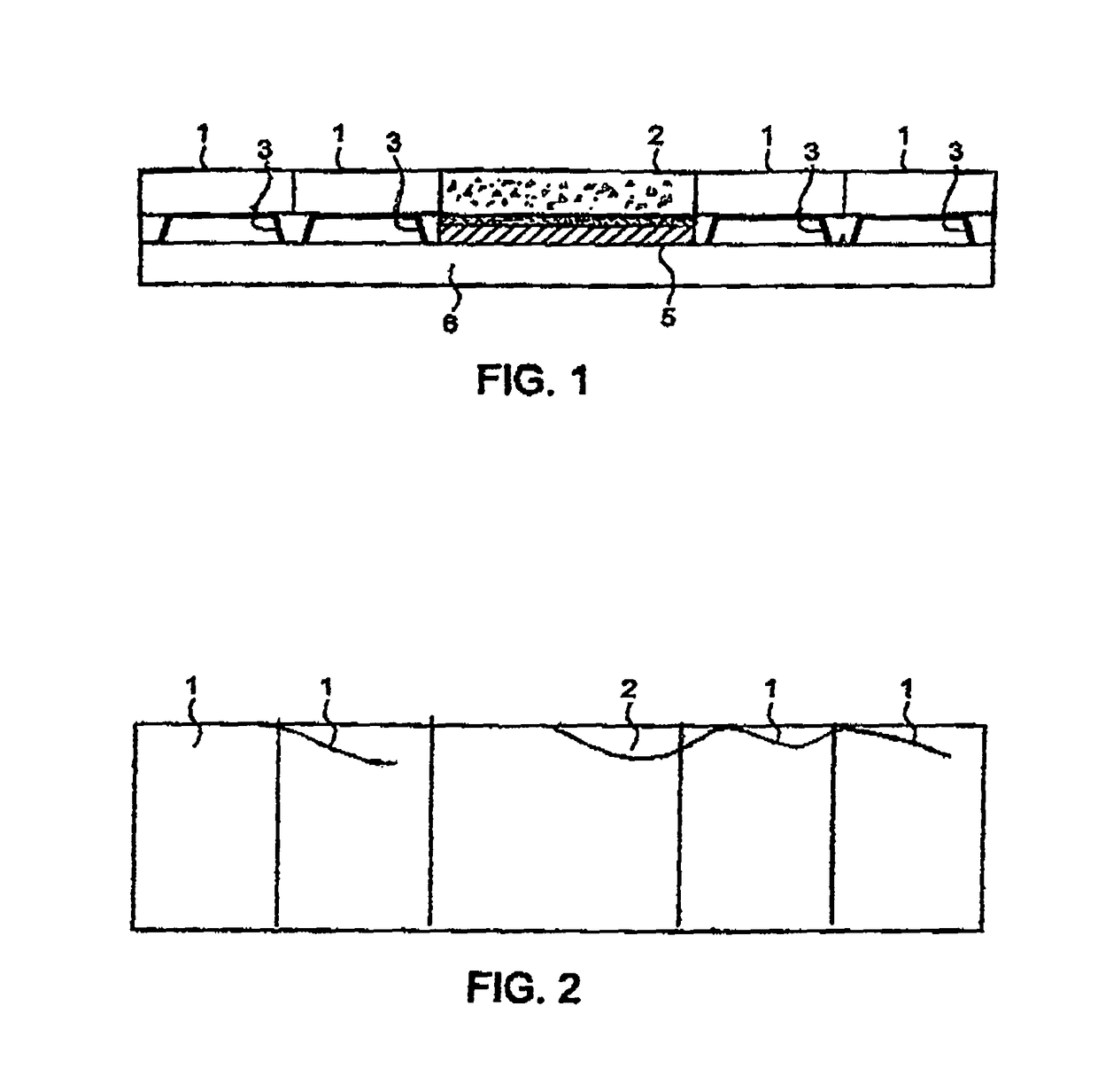
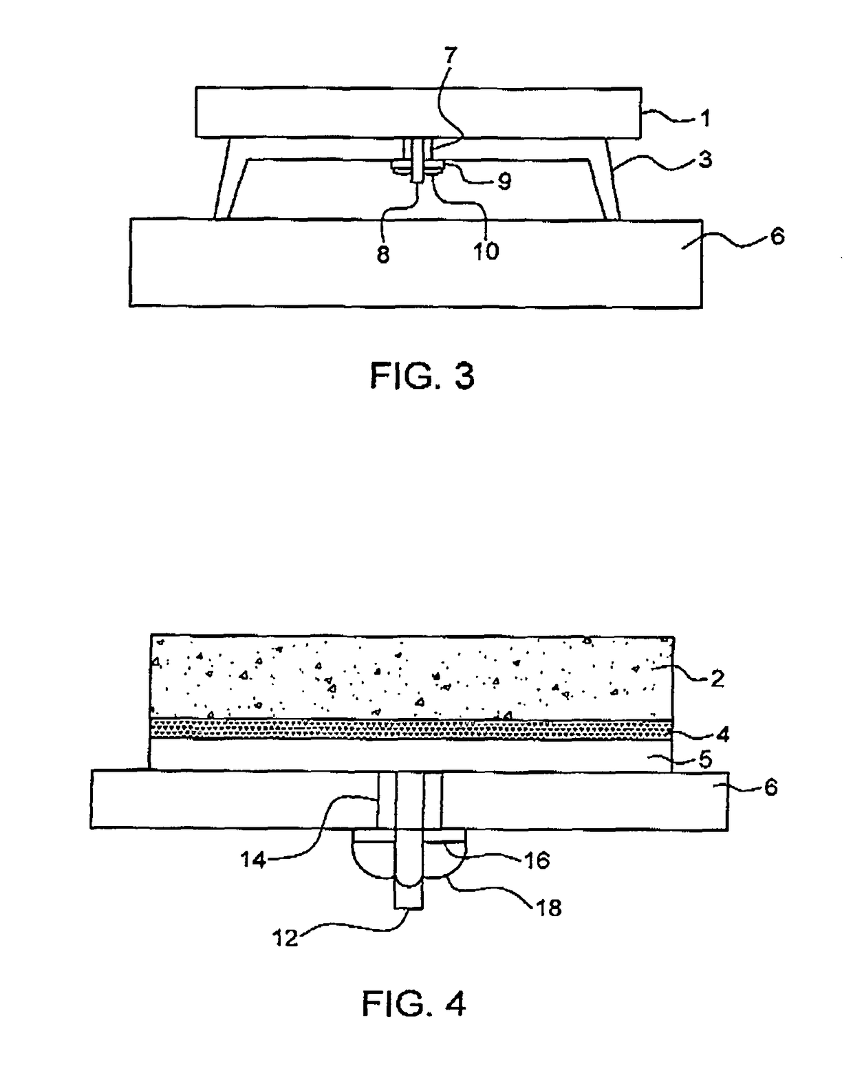
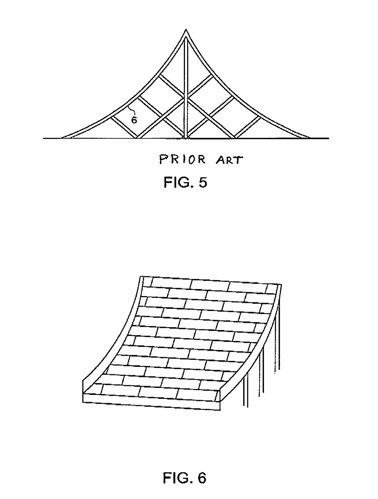
[0013]FIG. 1 schematically shows a metal backplate or substrate 6 of a flame deflector. An upper, rocket-facing surface of the backplate supports a plurality of modules 1, 2 which will be impacted by the flames and any debris coming out of the rocket. Suitable modules include metal bar or plate modules 1, preferably composed of a metal having high thermal conductivity, such as copper, carbon steel or alloy steel, and refractory material modules 2, preferably composed of a calcium aluminate cement (CAC) having high resistance to thermal degradation. During the Titan I program, mentioned above, a Portland cement was used; see standards ASTM C150 or European EN 197-1. The module has either a generally flat front face or a front face curved to conform to the shape of the metal deflector substrate, and four side faces, each orthogonal to the front face. The module has a rear face, adapted for attachment to a supporting metal substrate. Preferably, based upon the engine structure of the r...


PUM

PropertyMeasurementUnit
Temperatureaaaaaaaaaa
Electrical resistanceaaaaaaaaaa
Durabilityaaaaaaaaaa

Abstract

Flame deflectors for rocket launchpads have historically been constructed on-site by spraying on a layer of refractory cement material, resulting in large monolithic structures which lack durability and are vulnerable to degradation by ambient weather. By assembling together a plurality of metal modules and refractory material modules, one obtains a flame deflector structure whose set of modules is matched to an expected heat distribution pattern of the exhaust from the rocket to be launched. Further, modules can be prefabricated at another location, under controlled conditions, and subsequently installed. In case of damage during a launch, any damaged modules can be swapped out and replaced by new modules, thereby minimizing cost and downtime before a subsequent launch event. The modules can be made more weather-resistant by applying an epoxy sealant to their rocket-facing surfaces.

Description

CROSS-REFERENCES[0001]This application claims priority from my provisional application Ser. No. 62 / 497,119, filed Nov. 10, 2016, and incorporates by reference said provisional and the following technical literature:[0002]DATEAUTHOR(S)TITLE1966 MarchLays et al“Design Handbook for Protection of LaunchComplexes from Solid Propellent Exhaust,”prepared by Martin Marietta Co. forNASA-KSC (56 pages).2010 AprilCalle+“Refractory Materials for Flame DeflectorProtection,” (AIAA Conference Paper,10 pages).2009 JanuaryCalle+NASA / TM-2013-216316, “RefractoryMaterials for Flame Deflector ProtectionSystem Corrosion Control: CoatingsSystems Literature Survey”(17 pages).2009 JanuaryCalle+NASA / TM-2013-216321, “Refractory Materials for Flame Deflector ProtectionSystem Corrosion Control: Flame DeflectorProtection System Life CycleAnalysis Report” (74 pages).2009 JanuaryCalle+NASA / TM-2013-217910, “RefractoryMaterials for Flame Deflector ProtectionSystem Control: Similar Industriesand / or Launch Facilities ...

Claims


Application Information

Patent Timeline
IPC IPC(8): B64G5/00C23C30/00B05D3/02B05D7/14
CPCB64G5/00B05D7/14C23C30/005B05D3/0254
Inventor RENZI, PETER NICHOLAS
Owner RENZI FAMILY TRUST
Learn More