Determining a navigation image to be displayed

a navigation image and image technology, applied in image data processing, diagnostics, applications, etc., can solve the problems of information loss, inability to clearly distinguish from the directly adjacent background, etc., and achieve the effect of reducing the probability of features that are no longer visible in the navigation image, small dynamic result range, and large dynamic result rang

Active Publication Date: 2018-12-18
SIEMENS HEALTHCARE GMBH
View PDF8 Cites 1 Cited by
  • Summary
  • Abstract
  • Description
  • Claims
  • Application Information

AI Technical Summary

Benefits of technology

[0010]In this context, two disjoined color spaces may be used for the two subtraction images, wherein an increase in the distance between the color spaces is accompanied by enhanced visibility of the information shown in the navigation image. Moreover, when disjoined color spaces are used, there is no additive increase in the noise and so the existing signal-to-noise ratios remain unchanged.
[0013]In the event of a combination of color coding and dynamic compression, it is also particularly expedient for the dynamic compression of the at least one subtraction image to be used to enhance the legibility of the navigation image produced, as is explained in more detail below.
[0014]One particularly advantageous field of application of the method is obtained when the first subtraction image is an image of a blood vessel system of a patient, wherein the first X-ray image is recorded as a filled image with the administration of contrast medium in the blood vessel system and / or the second subtraction image is an image showing least one medical instrument located in the vascular system, wherein second X-ray images may be recorded cyclically. In this case, therefore, the navigation image is used for the navigation and tracking of a medical instrument during a medical intervention on the patient. The second X-ray images may then be recorded as fluoroscopy images, therefore with a low dose, so that although the instrument may be identified, the anatomy is displayed rather faintly. However, the first subtraction image provides a clear depiction of the relevant anatomy thus enabling excellent navigation, e.g., due to the good visibility of features, (e.g., information), from both subtraction images because of the preprocessing during the superimposition.
[0015]One advantageous development provides that, when features contained in the second subtraction image are displayed against a dark background of the first subtraction image, a color space extending from black to magenta is used for the second subtraction image or, when features contained in the second subtraction image are displayed against a light background of the first subtraction image, a color space extending from white to red is used for the second subtraction image. Experiments have shown that magenta on a dark background is particularly easy to identify and easy on the eye in the display, so that the use of a color space of this kind may be used in certain examples. Further useful color spaces in this context extend from black to yellow and / or from black to cyan. In the opposite case, it was established that red stands out particularly clearly from white.
[0017]In this context, one expedient development may provide that, in the case of features contained in both subtraction images in the same dynamic portion, at least one subtraction image is inverted before the superimposition within the context of the dynamic compression. Therefore, in this way the possibility is prevented, even in the case of different color coding, of the features remaining in the same dynamic portion in both images and this further greatly enhances the visibility and distinctiveness of features.

Problems solved by technology

Hence, in a subtraction image of this kind inverted before the superimposition, the vessels are not black, but white, so that, for example, on the superimposition of a medical instrument located at the edge of the vessel, clear differentiation from the directly adjacent background may not be possible: information is lost.

Method used


Image

  • Determining a navigation image to be displayed
  • Determining a navigation image to be displayed
  • Determining a navigation image to be displayed

Examples


Embodiment Construction

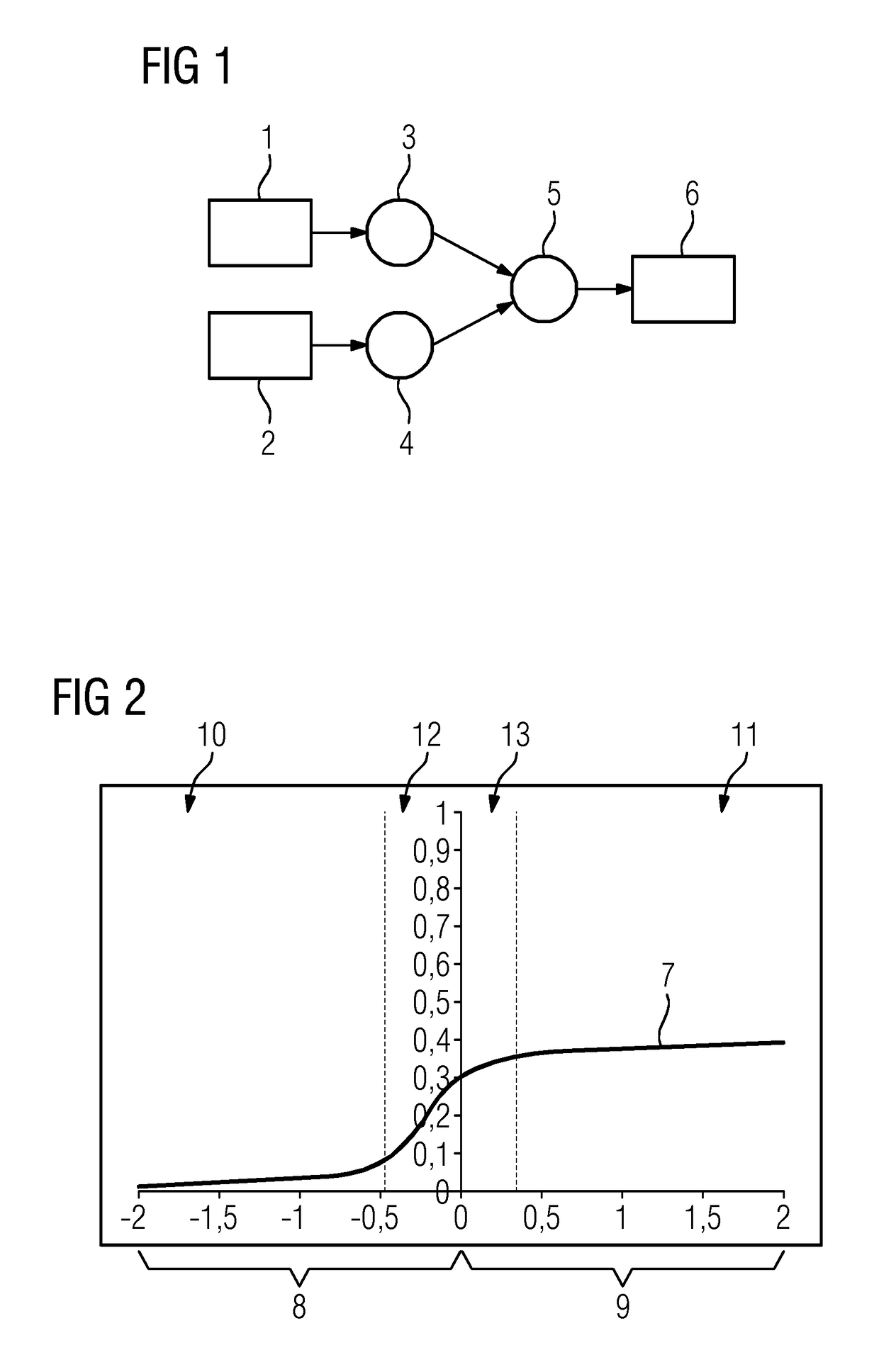
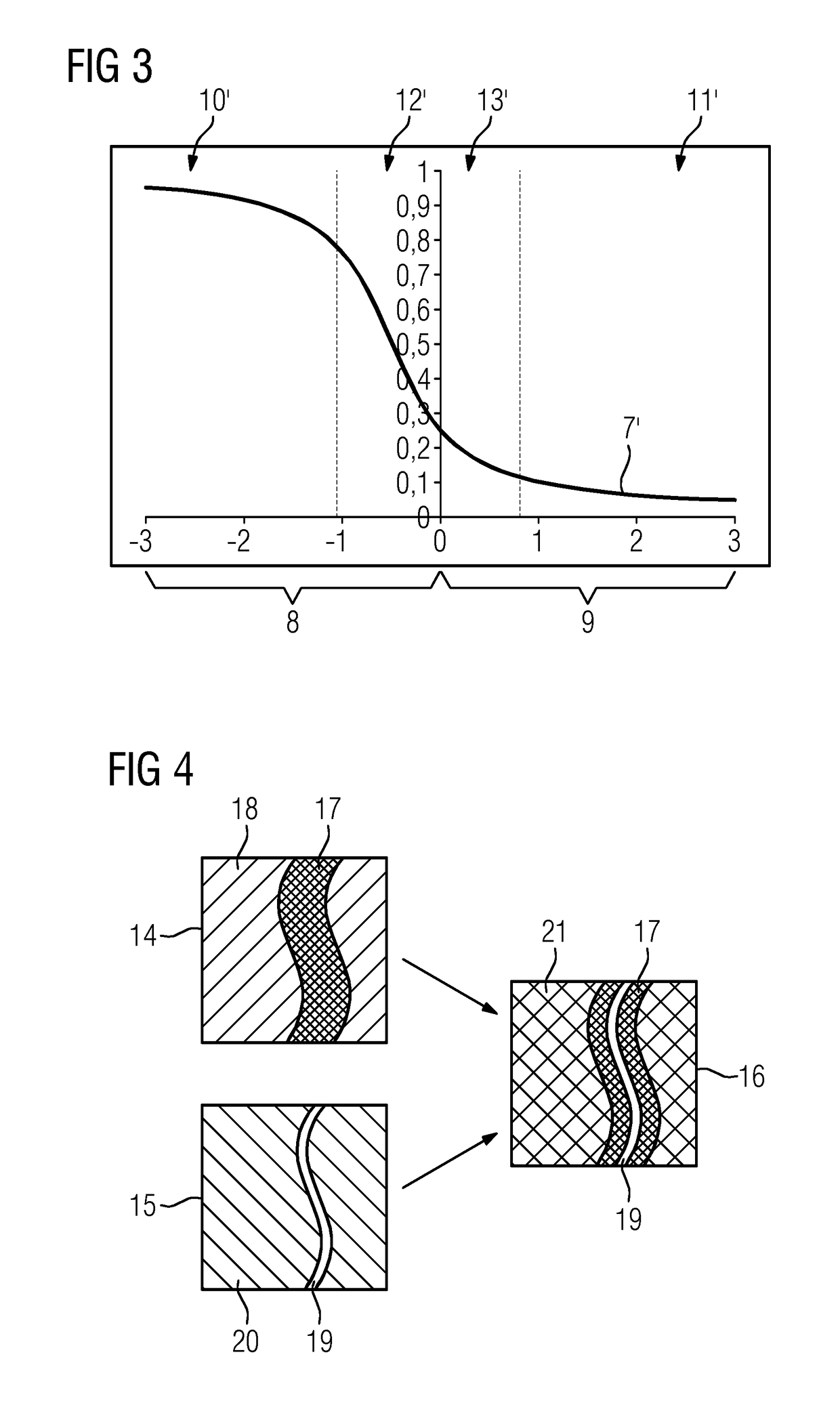
[0027]FIG. 1 is a diagram depicting a sequence of a method. In this case, the exemplary embodiments shown here relate to an application in which a navigation image is to be enabled that is as informative and identifiable as possible for monitoring the navigation of a medical instrument in a blood vessel system in a region of interest of a patient. To this end, two subtraction images compiled with an X-ray device are combined, namely a first subtraction image 1 (e.g., a blood-vessel system image) and a second subtraction image 2 (e.g., an instrument image). To determine the subtraction images, X-ray images are recorded in which the desired features, in particular highlighted, may be identified, from which a mask image recorded under the same conditions, without highlighting or without the medical instrument, which also entails an X-ray image of the region of interest, is subtracted. In the case of the first subtraction image 1, the X-ray image is recorded with contrast-medium-filled ...


PUM


Abstract

A method is provided for determining a navigation image displaying features of a region of interest of a patient, (e.g., used during a medical intervention). The method includes determining a first subtraction image by recording a first X-ray image with an X-ray device and subtracting a mask image. The method also includes determining a second subtraction image by recording a second X-ray image with the X-ray device and by subtracting the mask image or a further mask image. Additionally, the navigation image is determined by superimposing the first and the second subtraction image. At least one of the subtraction images is preprocessed before the superimposition by transfer from a gray-value space into a color space that is different from a color space of the other subtraction image. The navigation image is determined in color and / or the dynamics of at least one of the subtraction images are compressed.

Description

[0001]The application claims the benefit of DE 10 2016 201 702.0, filed Feb. 4, 2016, which is hereby incorporated by reference in its entirety.TECHNICAL FIELD[0002]The disclosure relates to a method for determining a navigation image displaying features of a region of interest of a patient, (e.g., used during a medical intervention), wherein: a first subtraction image is determined by recording a first X-ray image with an X-ray device and subtracting a mask image; a second subtraction image is determined by recording a second X-ray image with the X-ray device and by subtracting the mask image or a further mask image; and the navigation image is determined by superimposing the first and second subtraction image. The disclosure also relates to an X-ray device, a computer program, and an electronically readable data medium.BACKGROUND[0003]In medical X-ray-based imaging, subtraction techniques are used in body regions where there is relatively little movement, e.g., in the field of neu...

Claims


Application Information

Patent Timeline
Patent Type & Authority Patents(United States)
IPC IPC(8): G06T7/00A61B6/00G06T11/60G06T11/00
CPCG06T7/0016A61B6/5294G06T11/001G06T11/60G06T2207/30101G06T2207/10116G06T2207/20224G06T5/50A61B6/12A61B6/4441A61B6/481A61B6/487A61B6/504A61B6/5235
Inventor BERNHARDT, PHILIPP
Owner SIEMENS HEALTHCARE GMBH
Why Eureka
Try Eureka