AI technical title is built by Patsnap AI team. It summarizes the technical point description of the patent document.
a technology of exhaust gas and catalyst, which is applied in the direction of physical/chemical process catalyst, metal/metal-oxide/metal-hydroxide catalyst, separation process, etc., can solve the problems of increased pressure reducing combustion engine power, poor exhaust gas purification performance, etc., and achieve the effect of enhancing purification performance and reducing pressure loss
Active Publication Date: 2018-12-25
CATALER CORP +1
View PDF43 Cites 17 Cited by
Summary
Abstract
Description
Claims
Application Information
AI Technical Summary
This helps you quickly interpret patents by identifying the three key elements:
Problems solved by technology
Method used
Benefits of technology
Benefits of technology
[0013]The exhaust gas purification catalyst of Patent Document 1 has the Pd-containing layer and the Rh-containing layer separated as internal and external to the partition wall; and therefore, it is suited for inhibiting sintering of the catalytic metals. However, because the Pd-containing layer is present in the entire interior of the partition wall and the Rh-containing layer is placed to cover the surface of the partition wall, there is a problem of increased pressure reducing combustion engine power. On the other hand, with a focus placed on pressure loss, if, for instance, the coating densities of the catalytic layers are decreased, exhaust gas and the catalytic metals may have fewer opportunities for contact, resulting in poorer exhaust gas purification performance.
[0014]Lately, regulations on emissions and fuel consumption tend to be further tightened. Thus, with respect to an exhaust gas purification catalyst, along with reduction of pressure loss, further enhanced exhaust gas purification performance is desired.
[0015]The present invention has been made in view of these circumstances with an objective to provide a wall-flow-type exhaust gas purification catalyst that brings about both pressure loss reduction and enhancement of exhaust gas purification performance at a high level.
Problems solved by technology
However, because the Pd-containing layer is present in the entire interior of the partition wall and the Rh-containing layer is placed to cover the surface of the partition wall, there is a problem of increased pressure reducing combustion engine power.
On the other hand, with a focus placed on pressure loss, if, for instance, the coating densities of the catalytic layers are decreased, exhaust gas and the catalytic metals may have fewer opportunities for contact, resulting in poorer exhaust gas purification performance.
Method used
Image
Click on the blue label to locate the original text in one second.
Reading with bidirectional positioning of images and text.
Examples
example 11
[0170]First catalytic layer-forming slurry: 15.5 g alumina powder, 36.1 g zirconia-ceria composite oxide powder (zirconia / ceria=7 / 2), rhodium nitrate (0.2 g Rh)
[0171]Second catalytic layer-forming slurry: 11.4 g alumina powder, 17.2 g zirconia-ceria composite oxide powder (zirconia / ceria=7 / 2), 2.9 g barium sulfate, palladium nitrate (0.8 g Pd)
example 12
[0172]First catalytic layer-forming slurry: 17.5 g alumina powder, 40.7 g zirconia-ceria composite oxide powder (zirconia / ceria=7 / 2), rhodium nitrate (0.2 g Rh)
[0173]Second catalytic layer-forming slurry: 10.2 g alumina powder, 15.3 g zirconia-ceria composite oxide powder (zirconia / ceria=7 / 2), 2.6 g barium sulfate, palladium nitrate (0.8 g Pd)
example 13
[0174]First catalytic layer-forming slurry: 18 g alumina powder, 42 g zirconia-ceria composite oxide powder (zirconia / ceria=7 / 2), rhodium nitrate (0.2 g Rh)
[0175]Second catalytic layer-forming slurry: 10 g alumina powder, 15 g zirconia-ceria composite oxide powder (zirconia / ceria=7 / 2), 2.5 g barium sulfate, palladium nitrate (0.8 g Pd)
PUM
Property
Measurement
Unit
temperature
aaaaa
aaaaa
total length Lw
aaaaa
aaaaa
total length Lw
aaaaa
aaaaa
Abstract
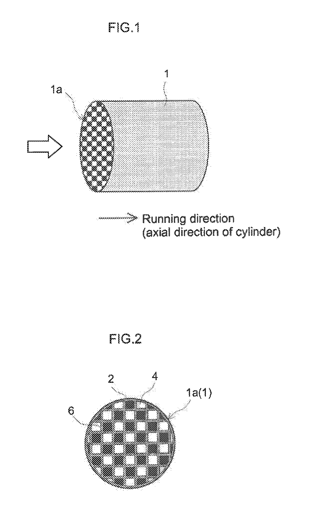
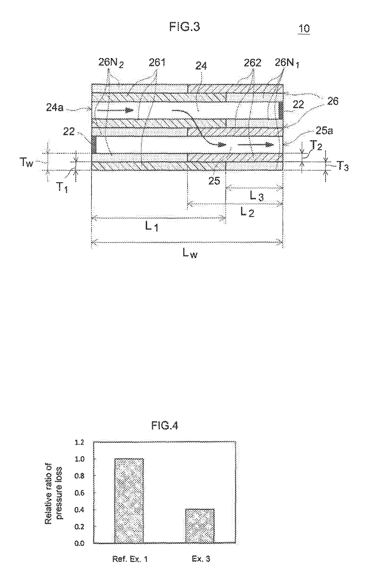
Provided is an exhaust gas purification catalyst that combines reduction of pressure loss and enhancement of purification performance. This invention provides an exhaust gas purification catalyst comprising a wall-flow-type substrate and first and second catalytic layers. The first catalytic layer is provided to the interior of a partition wall, in contact with an entrance cell, from an exhaust inlet-side end in the running direction, having a length L1 less than Lw. The second catalytic layer is provided to the interior of a partition wall, in contact with an exit cell, from an exhaust outlet-side end in the running direction, having a length L2 less than Lw. An internal portion of partition wall in contact with entrance cell has a substrate-exposing segment near the exhaust outlet-side end.
Description
TECHNICAL FIELD[0001]The present invention relates to an exhaust gas purification catalyst provided to an exhaust system of an internal combustion system. In particular, it relates to a wall-flow-type exhaust gas purification catalyst.[0002]The present application claims priority to Japanese Patent Application No. 2015-28796 filed on Feb. 17, 2015; the entire contents of which are incorporated herein by reference.BACKGROUND ART[0003]Exhaust gas emitted from an internal combustion system such as an automobile engine comprises toxic components such as particulate matter (PM), hydrocarbons (HC), carbon monoxide (CO), and nitrogen oxides (NOx). Conventionally, to efficiently eliminate these exhaust components, an exhaust purification catalyst having a catalytic layer is used, with the catalytic layer comprising a carrier and a catalytic metal supported on the carrier.[0004]For instance, a wall-flow-type exhaust gas purification catalyst comprises a wall-flow-type substrate and a catalyt...
Claims
Application Information
Patent Timeline
Application Date:The date an application was filed.
Publication Date:The date a patent or application was officially published.
First Publication Date:The earliest publication date of a patent with the same application number.
Issue Date:Publication date of the patent grant document.
PCT Entry Date:The Entry date of PCT National Phase.
Estimated Expiry Date:The statutory expiry date of a patent right according to the Patent Law, and it is the longest term of protection that the patent right can achieve without the termination of the patent right due to other reasons(Term extension factor has been taken into account ).
Invalid Date:Actual expiry date is based on effective date or publication date of legal transaction data of invalid patent.

