Method to determine performance of a chiller and chiller plant

a chiller and performance measurement technology, applied in the field of refrigeration systems, can solve the problems of single measurement (kw/ton), insufficient instrumentation and data collection system, and design of chiller plants without adequate efficiency measuremen

Active Publication Date: 2018-12-25
CHILLER PLANT OPTIMIZATION LLC
View PDF26 Cites 10 Cited by
  • Summary
  • Abstract
  • Description
  • Claims
  • Application Information

AI Technical Summary

Problems solved by technology

Many of today's modern designs for chiller plants do not include the instrumentation and data collection systems required for adequate efficiency measurements due to the complexity of the tabulated data and high cost of instrumentation.
For these reasons the instrumentation and data collection systems are not justified and not included in the plant's design.
There are significant difficulties with this single measure (kW/ton) since it will vary in either direction due to normal day to day operating conditions.
Consequently the measure is difficult to compare to a benchmark.
Therefore ASHRAE Guideline 22-2012 recognizes the short coming of just monit

Method used


Image

  • Method to determine performance of a chiller and chiller plant
  • Method to determine performance of a chiller and chiller plant
  • Method to determine performance of a chiller and chiller plant

Examples


Embodiment Construction

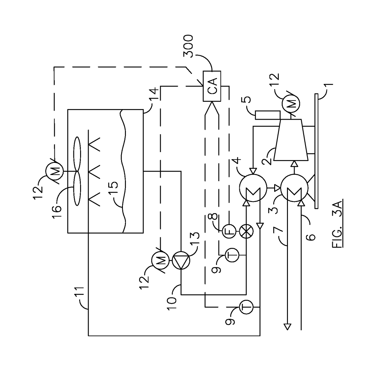
—FIGS. 3A, 5, 6A, 6B, 6C, 7A, 7B, 7C, 8 AND 9—FIRST EMBODIMENT

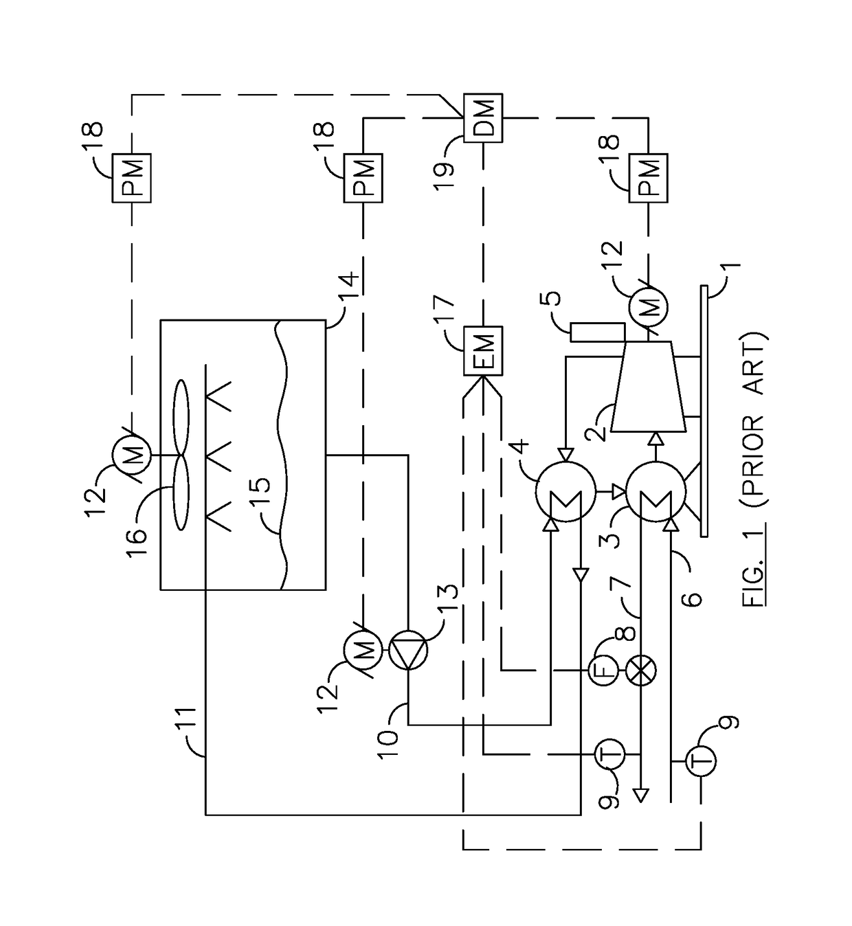
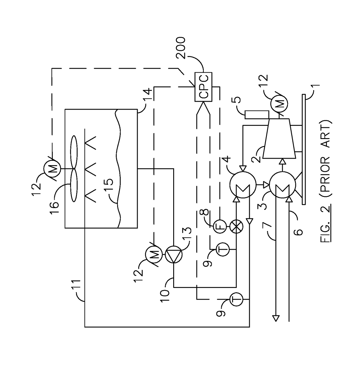
[0122]FIG. 3A illustrates a typical chiller plant with one chiller 1, one cooling tower 14, and one condenser water (CW) pump 13. These three units are connected by a piping circuit through which CW flows. The CW takes heat that is rejected by the chiller to the cooling tower where it is cooled and pumped back to the chiller refrigerant condenser 4.

[0123]Information required to determine chiller and chiller plant performance is readily collected with the instrumentation shown herein. A first temperature sensor 9 is installed in the entering condenser water (ECW) piping and a second temperature sensor 9 is installed in the leaving condenser water (LCW) piping 11. A flow meter 8 is installed to measure the flow rate of CW.

[0124]This real time data is read and collected from the instrumentation by computerized analyzer 300. In this embodiment the computerized analyzer 300 comprises a programmable logic computer (PLC) and a d...


PUM


Abstract

A chiller and chiller plant monitoring method that provides real time performance and benchmark parameters using condenser water temperatures and flow rates to determine crucial performance metrics. A customized chiller model developed with algorithms to make comparative analysis for different operating scenarios. By applying a customized model for the supporting equipment, the entire plant can be monitored for performance. Actual operational metrics are compared with bench mark models to provide real time analysis of energy demand. The model also produces a control formula for condenser water reset. And defining the plant as a chilled water production system separate from the distribution system allows comparison with many with dissimilar operations.

Description

CROSS REFERENCE TO RELATED APPLICATIONS[0001]This application claims the benefit of PPA Ser. No. 62 / 291,887, filed Feb. 5, 2016 by the present inventor which is incorporated by reference.[0002]This application uses the heat rejected by the chiller as disclosed in my U.S. Pat. No. 6,718,779 granted Apr. 13, 2004 which is incorporated by reference.BACKGROUNDPrior Art[0003]The following is a tabulation of some prior art that appears to be relevant:[0004]U.S. PatentsPat. No.Kind CodeIssue DatePatentee8,615,371B22013 Dec. 24Hegar8,424,322B22013 Apr. 23Seki8,393,169B22013 Mar. 12Pham8,322,155B22012 Dec. 4Tutunoglu8,316,658B22012 Nov. 27Singh7,945,423B22011 May 17Seigel6,718,779B12004 Apr. 13Henry5,083,438A1992 Jan. 28McMullin4,768,346A1988 Sep. 6Mathur4,507,930A1985 Apr. 2Kaya4,325,223A1982 Apr. 20Cantley[0005]U.S. Patent Application PublicationsPublication Nr.Kind CodePubl. DateApplicant20130031920A12013 Feb. 7Tegano20110023503A12011 Feb. 3Wang20090094998A12009 Apr. 16McSweeney2005022372...

Claims


Application Information

Patent Timeline
IPC IPC(8): F25B39/04G01M99/00F24F3/06G06F17/50F24F11/30F25B49/02F24F11/46
CPCF24F11/30G01M99/005F24F3/06G06F17/5086F25B2400/21G06F2217/80F25B49/02F24F11/46F25B25/005F25B49/00F25B2339/047F25B2400/06F25B2500/19F25B2700/21161G01M99/002G06F2111/10G06F30/20G06F2119/08
Inventor HENRY, WILLIAM R
Owner CHILLER PLANT OPTIMIZATION LLC
Why Eureka
Try Eureka