
Phase interpolator for interpolating phase of delay clock signal and device including the same and for performing data sampling by using phase interpolated clock signal

a delay clock and phase interpolator technology, applied in the field of phase interpolators, can solve the problems of slow operation speed of peripheral devices, speed difference between new microprocessors and peripheral devices, etc., and achieve the effect of improving circuit design size and device including, and reducing glitches

Active Publication Date: 2019-01-01
SAMSUNG ELECTRONICS CO LTD
View PDF19 Cites 3 Cited by
  • Summary
  • Abstract
  • Description
  • Claims
  • Application Information

AI Technical Summary

Benefits of technology

The patent text describes a new invention that helps reduce glitches and make electronic circuits smaller. This invention is called a phase interpolator.

Problems solved by technology

In spite of improvements of speed of peripheral devices, such as memory, communication devices, or graphic devices, and a data transmission rate, operating speeds of peripheral devices have not kept up with an operating speeds of processors, in some cases.
Further, a speed difference between new microprocessors and their peripheral devices is often present.

Method used


Image

  • Phase interpolator for interpolating phase of delay clock signal and device including the same and for performing data sampling by using phase interpolated clock signal
  • Phase interpolator for interpolating phase of delay clock signal and device including the same and for performing data sampling by using phase interpolated clock signal
  • Phase interpolator for interpolating phase of delay clock signal and device including the same and for performing data sampling by using phase interpolated clock signal

Examples


Embodiment Construction

[0030]As is traditional in the field of the inventive concepts, embodiments are described, and illustrated in the drawings, in terms of functional blocks, units and / or modules. Those skilled in the art will appreciate that these blocks, units and / or modules are physically implemented by electronic (or optical) circuits such as logic circuits, discrete components, microprocessors, hard-wired circuits, memory elements, wiring connections, and the like, which may be formed using semiconductor-based fabrication techniques or other manufacturing technologies. In the case of the blocks, units and / or modules being implemented by microprocessors or similar, they may be programmed using software (e.g., microcode) to perform various functions discussed herein and may optionally be driven by firmware and / or software. Alternatively, each block, unit and / or module may be implemented by dedicated hardware, or as a combination of dedicated hardware to perform some functions and a processor (e.g., ...


PUM


Abstract

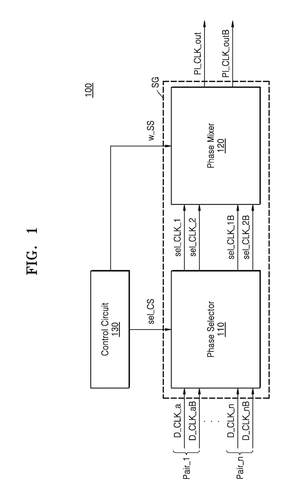
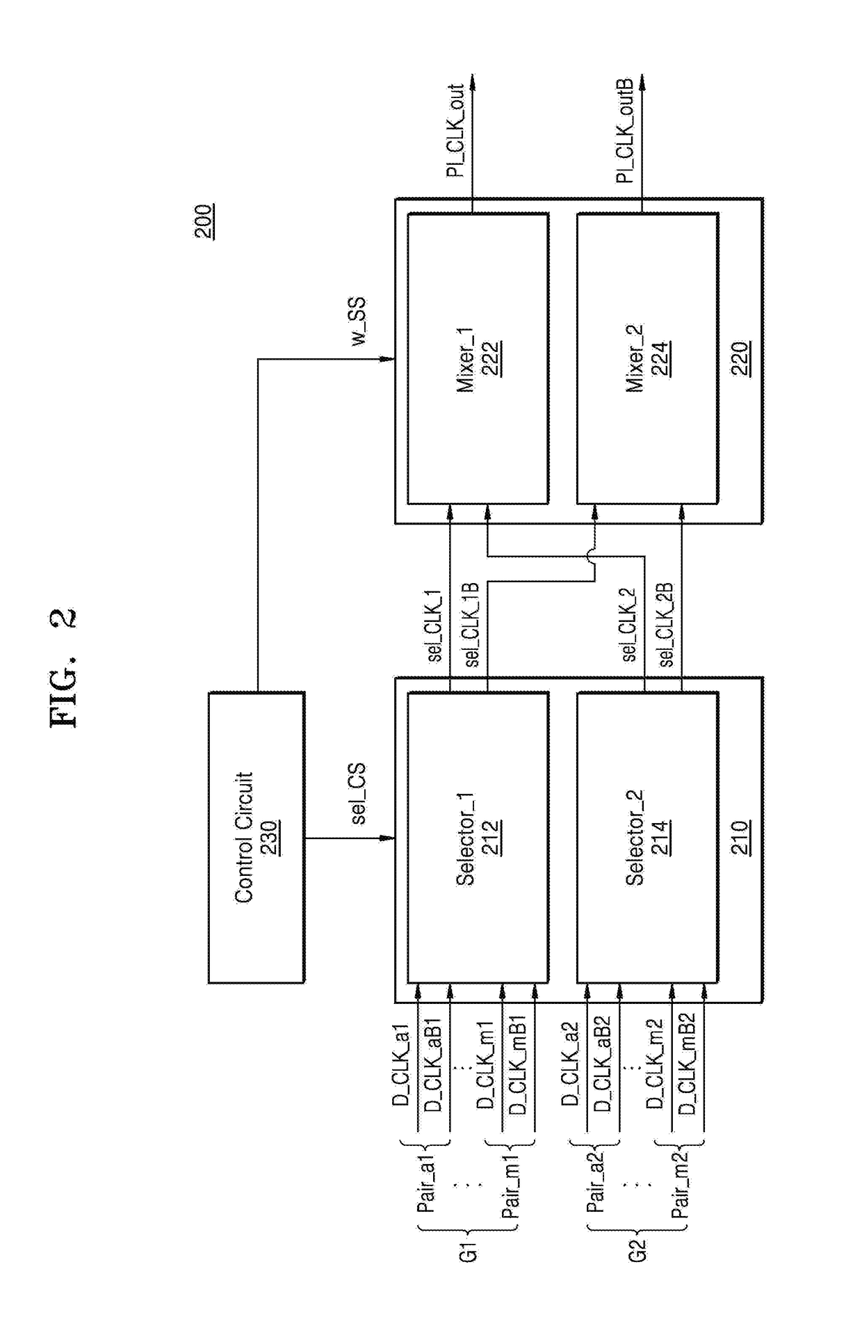
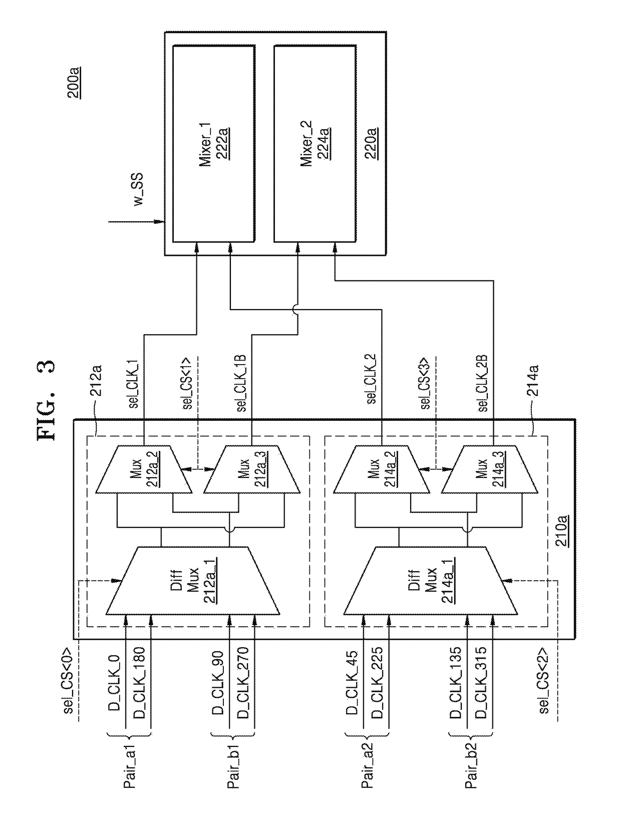
A phase interpolator includes a control circuit configured to generate a selection control signal that corresponds to a selected coarse phase interval, and generate a weight setting signal for generating a phase interpolation clock signal with an interpolated phase within the coarse phase interval; a phase selector configured to receive a plurality of inversion delay clock signal pairs, select at least two inversion delay clock signal pairs from the plurality of inversion delay clock signal pairs based on the selection control signal, select and output a selection delay clock signal pair corresponding to the coarse phase interval from the selected at least two inversion delay clock signal pairs; and a phase mixer configured to receive the selection delay clock signal pair from the phase selector and generate the phase interpolation clock signal based on the weight setting signal.

Description

CROSS-REFERENCE TO RELATED APPLICATION[0001]This application claims the benefit of Korean Patent Application No. 10-2016-0162295, filed on Nov. 30, 2016, in the Korean Intellectual Property Office, the disclosure of which is incorporated herein in its entirety by reference.BACKGROUND1. Field[0002]At least some example embodiments of the inventive concepts relate to a phase interpolator, and more particularly, to a phase interpolator for effectively interpolating a phase of a delay clock signal and a device including the same.2. Related Art[0003]In spite of improvements of speed of peripheral devices, such as memory, communication devices, or graphic devices, and a data transmission rate, operating speeds of peripheral devices have not kept up with an operating speeds of processors, in some cases. Further, a speed difference between new microprocessors and their peripheral devices is often present. Thus, some high performance digital systems have been required to dramatically improve...

Claims


Application Information

Patent Timeline
Patent Type & Authority Patents(United States)
IPC IPC(8): H04L7/04H04L7/033H03L7/081H04L7/00H03L7/08H03L7/07H03K5/131
CPCH03L7/0818H03L7/07H03L7/0807H03L7/0814H04L7/0037H04L7/0087H04L7/0331H04L7/0025H03K5/131H03L7/0998H03L7/18H04L7/0337H04L7/0338H03L7/0812H03L7/091H04L7/033
Inventor SONG, KYUNG-SEOKYOO, BYOUNG-JOOSEONG, CHANG-KYUNG
Owner SAMSUNG ELECTRONICS CO LTD
Learn More