Compressed data transmission in panel display system

a panel display and data transmission technology, applied in static indicating devices, cathode-ray tube indicators, instruments, etc., can solve the problems of increased baud rate and power consumption, limitation of the allowed amount of compressed data, display drivers suffering from a limitation of the number of bits for which the bit search can be performed in each clock cycl

Inactive Publication Date: 2019-01-08
SYNAPTICS INC
View PDF13 Cites 2 Cited by
  • Summary
  • Abstract
  • Description
  • Claims
  • Application Information

AI Technical Summary

Benefits of technology

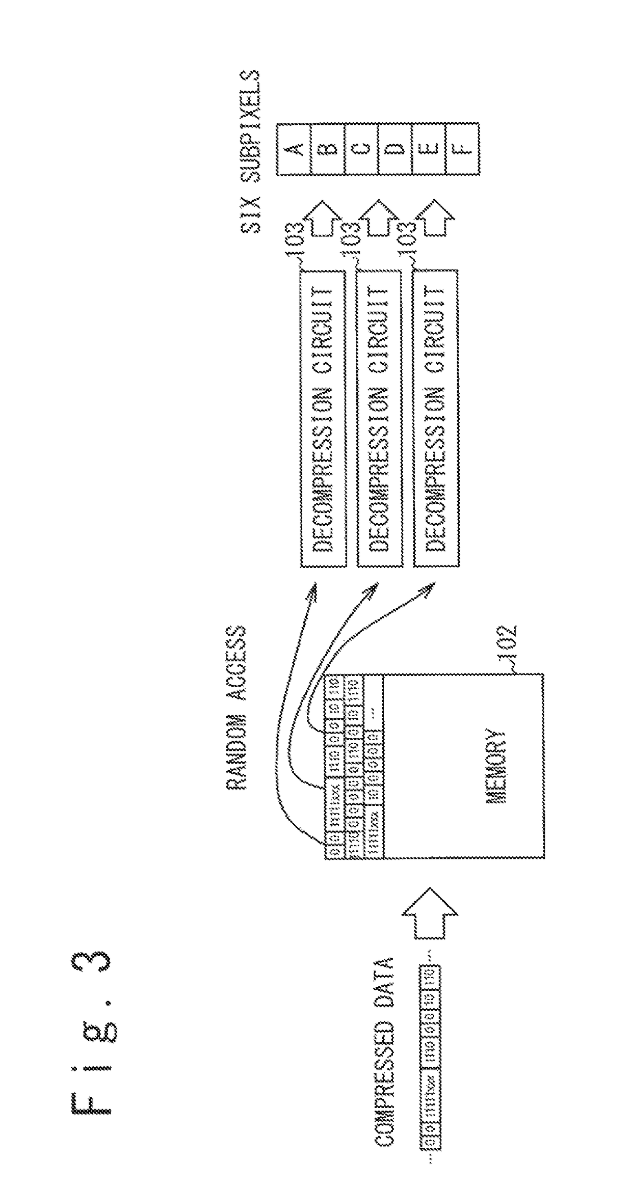
[0015]The present disclosure provides a technique for rapidly decompressing compressed data in a display driver in a panel display system configured to transmit the compressed data to the display driver.

Problems solved by technology

The increase in the data to be supplied to a display driver may cause increases in the baud rate and power consumption which are required for the data transfer to the display driver.
In a panel display system configured to transmit compressed data to a display driver, however, restrictions of hardware of the display driver may cause an issue.
When the compressed data is decompressed with a hardware circuit in the display driver, on the other hand, there is a limitation in the allowed amount of compressed data for which decompression processing is performed in each clock cycle.
This problem is especially significant when variable length compression is used in the data compression.
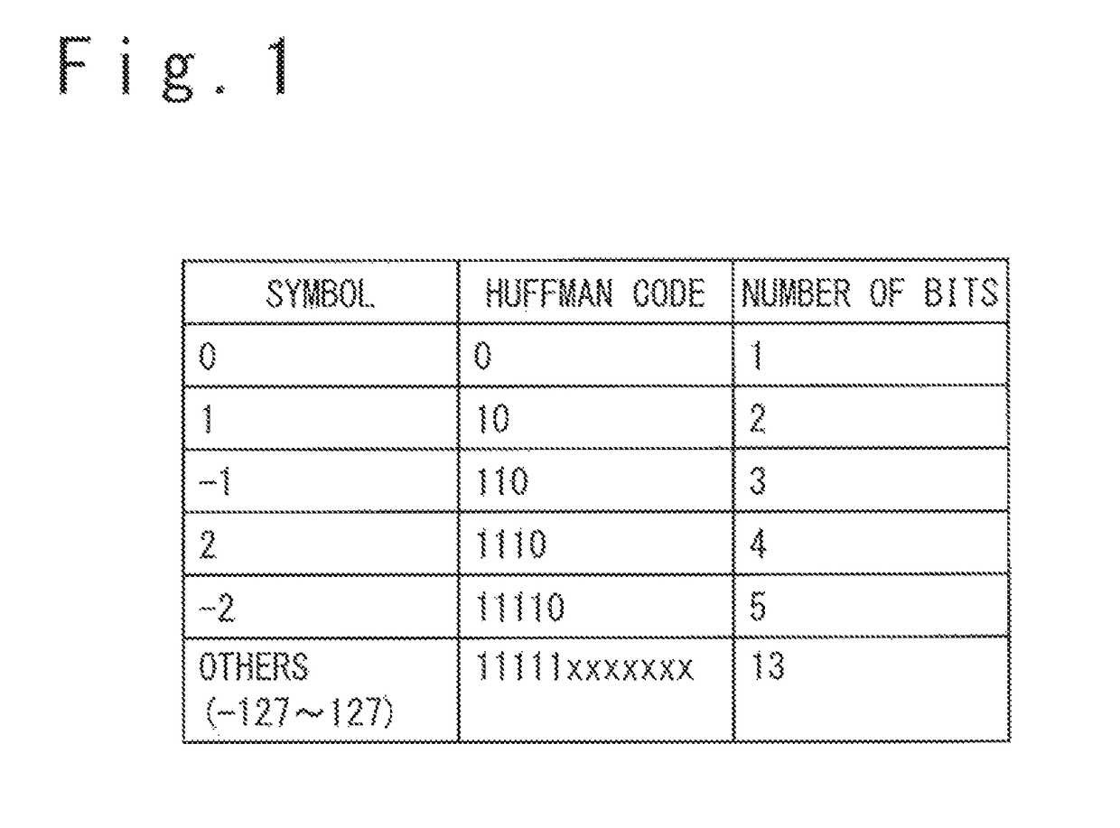
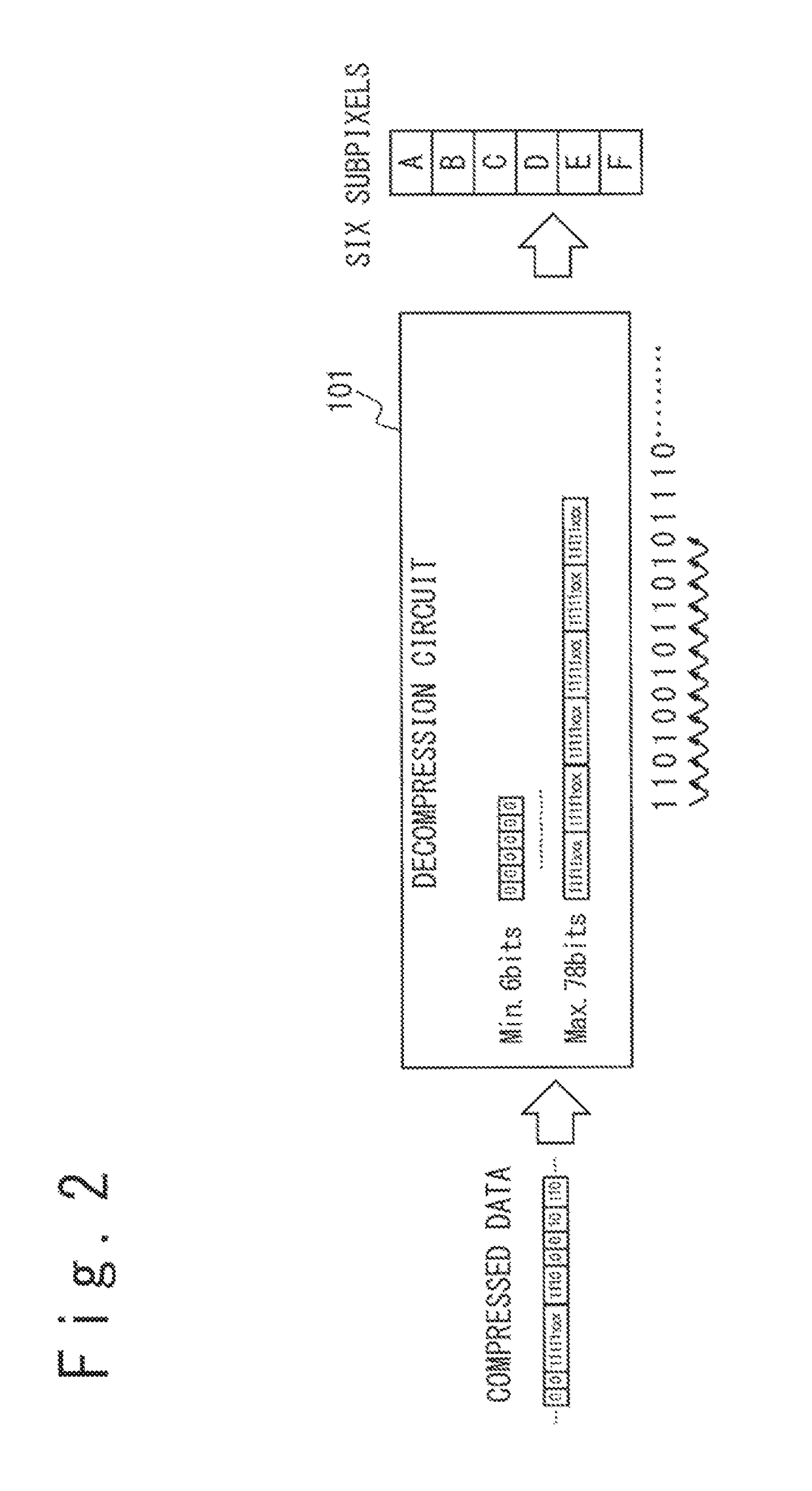
When a compressed data compressed through a variable length compression is decompressed, a bit search is perform to identify the end of each code and the value of each code; however, a display driver suffers from a limitation of the number of bits for which the bit search can be performed in each clock cycle.
The limitation of the number of bits for which the bit search can be performed is significant especially when a long code length is allowed in the variable length compression.

Method used


Image

  • Compressed data transmission in panel display system
  • Compressed data transmission in panel display system
  • Compressed data transmission in panel display system

Examples


first embodiment

[0044]FIG. 5 is a block diagram illustrating the configuration of a display system 10 in a first embodiment. The display system 10 illustrated in FIG. 1 includes a display panel 1, a host device 2 and a display driver 3. An OLED (Organic Light Emitting Diode) display panel or a liquid crystal display panel may be used as the display panel 1, for example.

[0045]The display panel 1 includes scan lines 4, data lines 5, pixel circuits 6 and scan driver circuits 7. Each of the pixel circuits 6 is disposed at an intersection of a scan line 4 and a data line 5 and configured to display a selected one of the red, green and blue colors. The pixel circuits 6 displaying the red color are used as R subpixels. Similarly, the pixel circuits 6 displaying the green color are used as G subpixels, and the pixel circuits 6 displaying the blue color are used as B subpixels. When an OLED display panel is used as the display panel 1, the pixel circuits 6 displaying the red color include an OLED element em...

second embodiment

[0094]FIG. 11 is a block diagram illustrating the configuration of the display system 10A, more particularly, the configuration the display driver 3A in a second embodiment. The configuration of the display system 10A of the second embodiment is similar to that of the display system 10 of the first embodiment. In the second embodiment, however, a memory 61 and an image decompression circuitry 62 are provided in the display driver 3A in place of the memory 24 and the correction data decompression circuitry 25.

[0095]The display system 10A of the second embodiment is configured so that the host device 2 generates compressed image data 46 by compressing image data corresponding to an image to be displayed on the display panel 1 and supplies the compressed image data 46 to the display driver 3A. In the second embodiment, the compression process in which the host device 2 compresses the image data to generate the compressed image data 46 is the same as the compression process in which the...

third embodiment

[0120]FIG. 15 is a block diagram illustrating the configuration of the display system 10B, more particularly to a display driver 3B in a third embodiment. The configuration of the display system 10B of the third embodiment is similar to those of the display system 10 of the first embodiment and the display system 10A of the second embodiment. It should be noted however that the display system 10B of the third embodiment is configured to be adapted to both of the operations of the display system 10 of the first embodiment and the display system 10A of the second embodiment. The display system 10B of the third embodiment is configured to selectively perform a selected one of the operations of the first and second embodiments, in response to the setting of the operation mode.

[0121]In the third embodiment, the display driver 3B includes the correction calculation circuitry 22, the correction data decompression circuitry 25, the image decompression circuitry 62, a memory 71 and a selecto...


PUM


Abstract

A host device divides original data into first to Nth stream data for N being an integer of two or more, generates first to Nth compressed stream data by sequentially compressing the first to Nth stream data with a variable length compression, divides the first to Nth compressed stream data into fixed-length blocks, and sequentially transmits the fixed-length blocks to the display driver. The display driver includes a memory storing therein the fixed-length blocks and a decompression circuitry reading out the fixed-length blocks from the memory. The decompression circuitry includes first to Nth processing circuits. The first to Nth processing circuits each perform a predetermined process on the fixed-length blocks received to generate processed data. The host device sorts the fixed-length blocks so that the fixed-length blocks are supplied in the order in which the first to Nth processing circuits require the fixed-length blocks.

Description

TECHNICAL FIELD[0001]The present invention relates to a display system, a host device and a non-transitory storage medium, more particularly, transfer of compressed data in a panel display system including a display panel.BACKGROUND ART[0002]In a panel display system including a display panel, data associated with respective subpixels of respective pixels of the display panel are transmitted to a display driver which drives the display panel. Such data may include, for example, image data specifying the grayscale values of the respective subpixels of the respective pixels and correction data associated with the respective subpixels of the respective pixels. The correction data referred herein is data used in a correction calculation of image data to improve the image quality. Recently, the number of pixels of a display panel to be driven by a display driver is increased, and this causes an increase in the amount of data to be supplied to the display driver. The increase in the data ...

Claims


Application Information

Patent Timeline
Patent Type & Authority Patents(United States)
IPC IPC(8): G09G5/395G09G3/3291G09G3/3258
CPCG09G3/3258G09G3/3291G09G5/395G09G2350/00G09G2320/0626G09G2330/028G09G2340/02G09G2300/0439G09G3/2011G09G2310/027G09G2320/0271G09G2320/0285G09G3/3275
Inventor FURIHATA, HIROBUMIBERGET, DAMIENNOSE, TAKASHIREYNOLDS, JOSEPH KURTH
Owner SYNAPTICS INC
Why Eureka
Try Eureka