Right and left motor output control for vehicle

a technology of output control and right and left motor, which is applied in the field of vehicles, can solve the problems of deteriorating driving in relation to turning of the vehicle, and achieve the effects of preventing damage to the energy storage device, ensuring the turning performance of the vehicle, and reducing the risk of accidents

Active Publication Date: 2019-01-15
HONDA MOTOR CO LTD
View PDF25 Cites 5 Cited by
  • Summary
  • Abstract
  • Description
  • Claims
  • Application Information

AI Technical Summary

Benefits of technology

[0009]The present invention has been devised in relation to the techniques and problems mentioned, above, and has the object of providing a vehicle, in which, in the case that even a small amount of residual capacity (SOC: State of Charge) of a discharge power (outflowing power) in relation to driving of the left and right motors from the energy storage device remains, excessive discharging of the energy storage device is protected against, together with improving drivability in relation to turning of the vehicle.
[0011]According to the present invention, when the output power is limited, for example, by the energy storage device being at a low temperature or the like, by controlling the difference (difference or ratio) between the left motive force and the right motive force on the basis of such a limitation, damage to the energy storage device due to excessive discharging or the like can be prevented, while the turning performance of the vehicle can be ensured by carrying out a turning directional control.
[0012]In this case, the motor control device may determine the maximum value of the difference based on a consumable power that is capable of being consumed by the left motor and the right motor, which is determined on a basis of the temperature of the energy storage device or the maximum output power of the energy storage device, and a correspondence relationship between the difference between the left motive force and the right motive force and a power loss at a time that the difference is generated. In this manner, it is possible to more reliably protect the maximum output power of the energy storage device.
[0014]By controlling the left and right sum of the left motive force and the right motive force so as to become substantially zero, the power loss, which may occur in accordance with the left and right difference, increases, whereby it is possible for the power consumed by the sum total of the left and right motors to be reduced, and for the maximum value of the left and right difference (power difference) to be increased in value.
[0015]Furthermore, the vehicle comprises an internal combustion engine and a generator configured to be driven by the internal combustion engine and connected electrically to the energy storage device, and at a time that the vehicle is currently traveling, and occurrence of a period in which the generator cannot generate electricity is predicted or detected, then within the period in which electricity cannot be generated, the motor control device is configured to control the left motive force and the right motive force of the left motor and the right motor so as not to exceed the maximum value of the difference between the left motive force and the right motive force, which is determined on a basis of the temperature of the energy storage device or the maximum output power of the energy storage device. In accordance therewith, even in a period in which the generator cannot generate electricity, damage to the energy storage device can be prevented, and by carrying out the turning control of the vehicle, the turning performance of the vehicle can be ensured.
[0016]According to the present invention, even when the output power is narrowed by the energy storage device being at a low temperature or the like, it is possible for a maximum differential torque to be generated, whereby under various conditions, the turning performance of the vehicle can be maintained, and as a result, a deterioration in drivability under a low temperature condition or the like can be suppressed.

Problems solved by technology

However, in the event that the vehicle is driven to make a turn by such a zero power control during turning (i.e., a control to make the discharge power (outflowing power) in relation to driving of the left and right motors from the energy storage device a zero value), a motive force is generated at all times in the vehicle in the direction of deceleration, and in a situation when acceleration during turning is desired, for example, when traveling at a constant turning speed or when exiting from a curve, drivability in relation to turning of the vehicle is deteriorated.

Method used


Image

  • Right and left motor output control for vehicle
  • Right and left motor output control for vehicle
  • Right and left motor output control for vehicle

Examples


Embodiment Construction

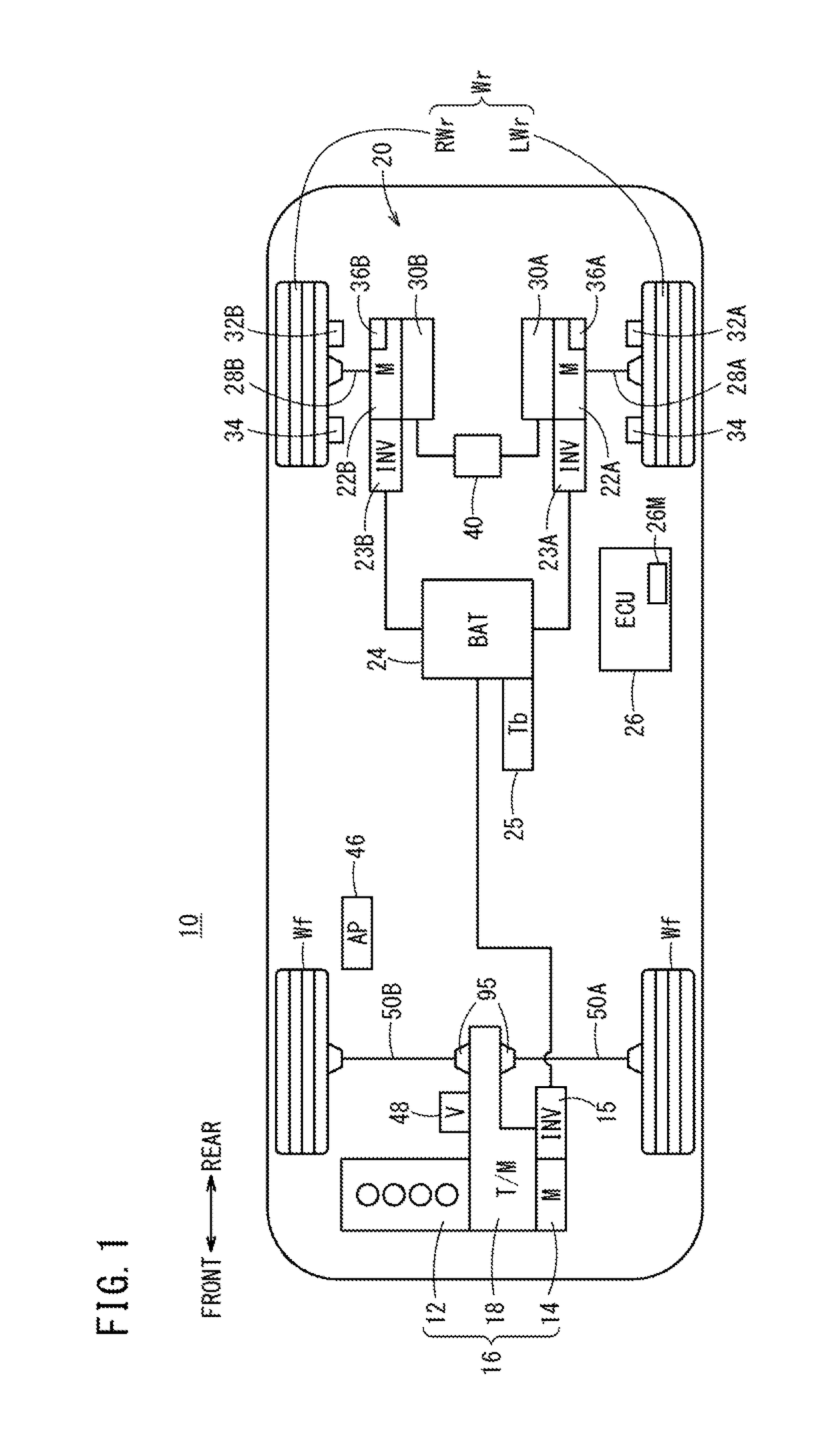
[0033]FIG. 1 is a block diagram showing in outline the configuration of a vehicle 10 according to an embodiment of the present invention.

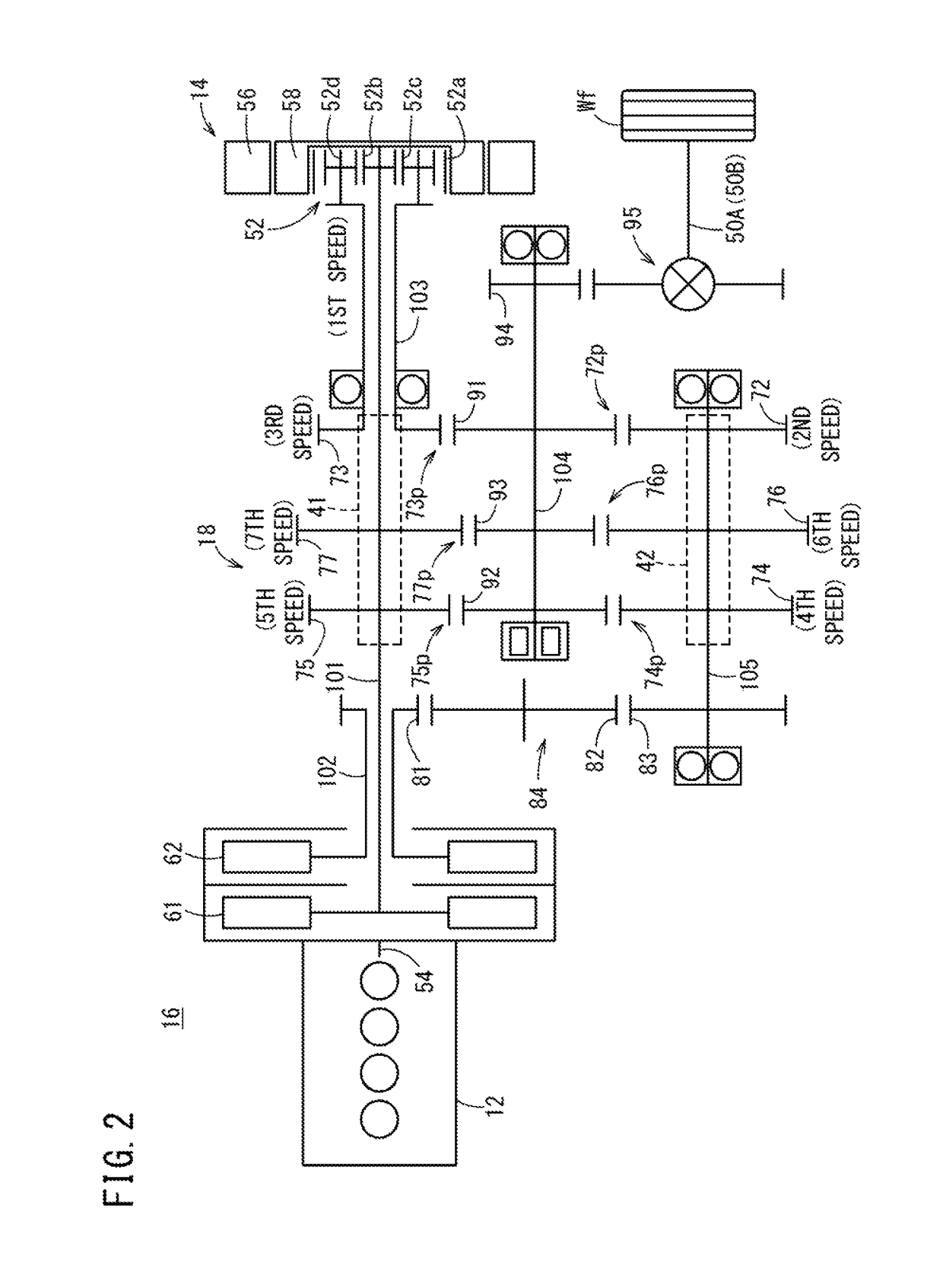
[0034]The vehicle 10 is a hybrid vehicle, which includes on a front part of the vehicle a drive device 16 (second drive device, hereinafter referred to as a front wheel drive device) in which a motor (M) 14 is connected in series through a transmission (T / M) 18 to an internal combustion engine 12. Motive power from the internal combustion engine 12 and the motor 14 is transmitted to the front wheels Wf through the transmission 18, whereas motive power of a drive device 20 (first drive device, hereinafter referred to as a rear wheel drive device) disposed on a rear part of the vehicle separately from the front wheel drive device 16 is transmitted to the rear wheels Wr (RWr, LMr).

[0035]The motor 14 of the front wheel drive device 16 and left and right motors (M) 22A, 22B (first and second motors) of the rear wheel drive device 20 are each connected e...


PUM


Abstract

Provided is a vehicle in which overdischarge of a battery is protected and turning drivability of the vehicle is improved when there is even a little remaining capacity. An ECU controls the left motive force and the right motive force of the left electric motor and the right electric motor so as not to exceed a differential torque upper limit value, which is the maximum value of the difference between the left motive force and the right motive force established on the basis of the temperature or discharge limit power of the battery. When the battery is at a low temperature or the like and the discharge power is limited, the difference between the left motive force and the right motive force is controlled on the basis of the discharge limit power, whereby the turnability of the vehicle is improved while preventing the risk of damage to the battery.

Description

TECHNICAL FIELD[0001]The present invention relates to a vehicle in which at least one of a front wheel pair (left front wheel and right front wheel) and a rear wheel pair (left rear wheel and right rear wheel) is driven by left and right electric motors.BACKGROUND ART[0002]In FIG. 1 of International Publication No. WO2013 / 005733 (hereinafter referred to as WO2013 / 005783A), there is disclosed an all-wheel drive (AWD) capable vehicle equipped with left and right electric motors for driving the rear wheels (left rear wheel and right rear wheel), an electric motor that can also function as a generator connected mechanically to an internal combustion engine that drives the front wheels (left front wheel and right front wheel), an energy storage device connected electrically to the left and right electric motors and to the electric motor that also functions as a generator, and a motor controller that controls the aforementioned three electric motors.[0003]In FIG. 1, etc., of Japanese Laid...

Claims


Application Information

Patent Timeline
Patent Type & Authority Patents(United States)
IPC IPC(8): B60K6/00B60W30/045B60W10/08B60W10/26B60W20/00B60K6/48B60W30/18B60W20/13B60K6/52B60L15/20B60W20/10B60L3/00B60K7/00B60L50/15B60L50/16
CPCB60K6/52B60L3/0046B60L11/12B60L11/14B60L11/1859B60L15/2036B60L15/2045B60W10/08B60W10/26B60W20/00B60W20/10B60W20/13B60W30/045B60W30/18145B60K6/48Y10S903/916B60K7/0007B60L2220/42B60L2240/545B60L2260/28B60W2510/246B60W2710/083B60W2720/406B60Y2200/92B60Y2300/188B60Y2300/60B60Y2300/91B60Y2400/82Y02T10/6221Y02T10/6265Y02T10/645Y02T10/705Y02T10/7005Y02T10/7283B60L58/14B60L58/24Y02T10/62Y02T10/64Y02T10/70Y02T10/72B60L15/20
Inventor TERAYAMA, YOSHITONEGORO, MASAKIHONDA, TOMOKAZUKOBAYASHI, AKIYOSHIYOSHIMI, SHINTARONAKAMURA, YOSHIFUMI
Owner HONDA MOTOR CO LTD
Why Eureka
Try Eureka