
Portable cable tie tool

a technology of cable tie and tool, which is applied in the field of portable tools, can solve the problems of reduced reproducibility, abrasive wear which arises in the course of its course, and the traction force exerted by the teeth of the tensioning roller is no longer sufficient for onward movement, so as to improve the reproducibility of strap tension and ensure the effect of reliable synchronization of the procedur

Active Publication Date: 2019-01-15
HELLERMANN TYTON GMBH
View PDF20 Cites 0 Cited by
  • Summary
  • Abstract
  • Description
  • Claims
  • Application Information

AI Technical Summary

Benefits of technology

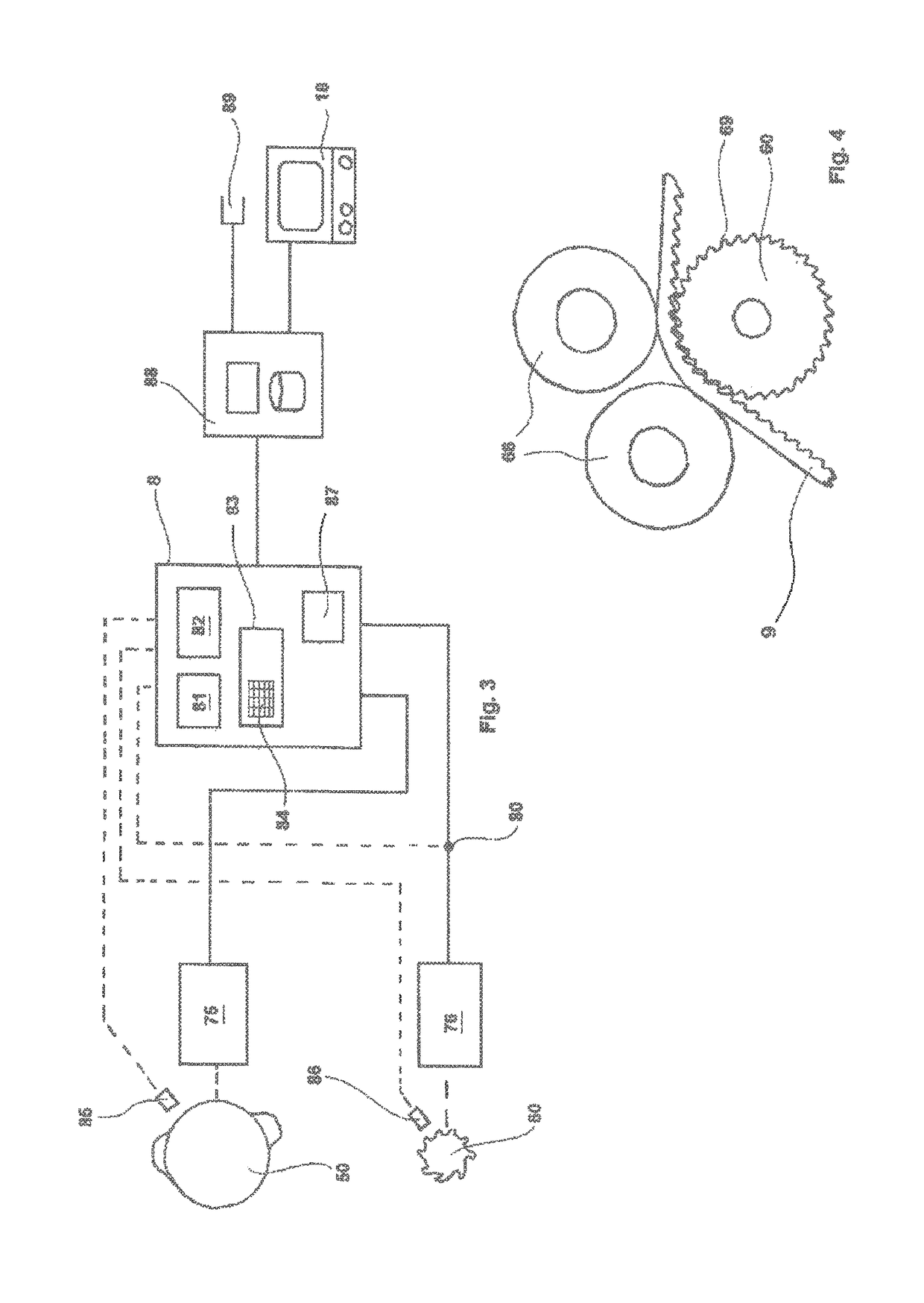
[0008]An aspect of the invention is based on the concept of providing one dedicated drive each for the cycle controller, on the one hand, and for the tensioning installation, on the other hand. Thus, by providing a dedicated drive for the tensioning installation, this drive is free of interferences caused by the cycle controller. More precise tensioning by means of the tensioning installation may thus be performed. The desired strap tension may be more accurately achieved in this way such that the fastening quality is improved. The result of the tying procedure is thus a secure fit having high reproducibility in terms of the strap tension. A torque-control installation for the drive of the tensioning installation is preferably provided. Said torque-control installation enables precise monitoring of the torque acting on the tensioning installation and thus also of the strap tension caused thereby. The actually achieved strap tension may thus be checked in real time during tensioning. On account thereof, reproducibility is further enhanced. Furthermore, such torque control enables rupture identification. A rupture is characterized in that a rise in the torque of the tensioning installation is followed by a rapid drop, since there is no longer any strap tension as a result of the strap rupture. Process reliability is significantly enhanced by such rupture identification.
[0017]The portable tool furthermore preferably has a storage installation which comprises data sets relating to maximum current, average current, holding time, and / or cycle time of the tensioning procedure. A capability of documenting the tensioning procedure is achieved in this way. Since, thanks to the separation according to the invention of the tensioning drive from the cycle controller, the current input by the tensioning drive serves exclusively for tensioning the strap, a capability for documenting may be achieved in this way in an expedient and efficient manner by way of simple measurement of the current input of the tensioning installation. Interference factors by virtue of other procedures of the cycle controller, for example by virtue of friction on the strap, thus do not have any interfering effect. A meaningful documentation of high quality may thus be achieved in a startlingly simple manner. In this way, tying quality is rendered traceable and may be evaluated in the context of measures which per se are usual in the industry, for example in the context of statistical process monitoring. This may also be performed in a localized manner in the context of rupture identification on the strap by the respective control installation.

Problems solved by technology

Once the strap reaches its pre-determined strap tension the traction force which is exerted by the teeth of the tensioning roller is no longer sufficient for onward movement, so that the strap is stationary and the teeth of the tensioning roller machine themselves into the surface of the strap.
Even if the weakening of the strap material, which is invariably associated therewith, in practical terms is mostly of no further consequence, the abrasive wear which arises in the course thereof is indeed objectionable.
In the case of such a friction clutch there is the issue of reduced reproducibility as a result of wear.
Thus, while the abrasive wear as arises in the first mentioned solution is indeed avoided, uniform quality of strap tension does suffer in this case.

Method used


Image

  • Portable cable tie tool
  • Portable cable tie tool

Examples


Embodiment Construction

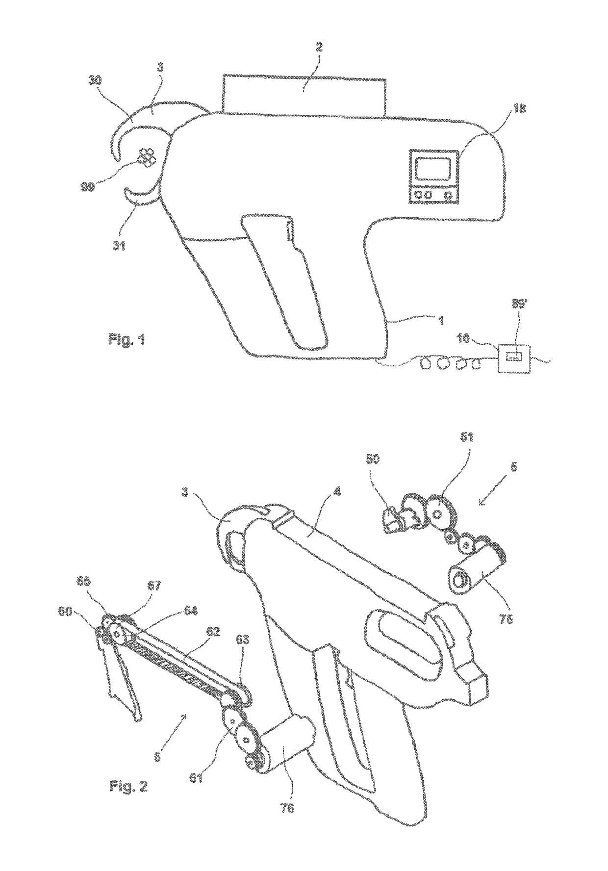
[0024]A portable tying tool in the illustrated exemplary embodiment is provided for processing cable ties 3. The tying tool comprises a tool body 1 having at the lower end thereof a pistol-type handle. A removable magazine 2 is provided at the upper end of said tool body 1, said magazine 2 receiving the cable ties 9 to be supplied. A clamp 3, which of two clamp halves 30, 31 which are moveable in relation to one another, is disposed on a front side of the tool body 1. The tool body on the lateral face thereof has a command panel 18 having a display and input keys. A power pack 10 is provided for providing power.

[0025]During operation, the object to be tied (cable strand 99) is moved in between the opened clamp halves 30, 31. The clamp halves 30, 31 converge, thus closing the clamp 3. Here, a cable tie 9, by way of the leading free end thereof, is indexed through a guide groove (not illustrated) on the internal side of the clamp 3 and guided around the cable strand 99 in such a fashi...


PUM


Abstract

A portable tool for tying an object, in particular a cable harness, using a strip, comprising a tool element with a cycle controller arranged in the tool element, a clamping device, and a drive for the clamping device. The drive is designed as a dual drive such that the cycle controller and the clamping device each have a dedicated drive, said drives being actuated independently by a controller. By providing a dedicated drive for the clamping device in this manner, interfering influences from the cycle controller are eliminated. Thus, a more precise clamping process can be carried out with high reproducibility, thereby improving the quality of the tying process.

Description

CROSS-REFERENCE TO RELATED APPLICATIONS[0001]This application is a national stage application under 35 USC 371 of International Application No. PCT / EP2014 / 072056, filed Oct. 14, 2014, which claims priority to German Application No. 10 2013 222 924.0, filed Nov. 11, 2013, the entire contents of which are incorporated herein by reference.FIELD OF THE INVENTION[0002]The invention relates to a portable tool for tying an object, in particular a cable harness, by means of a strap, said portable tool having a tool body with a cycle controller disposed therein, and a tensioning installation and a drive therefor.BACKGROUND OF THE INVENTION[0003]In the case of known cable tie tools such as are known in principle from EP 0 428 116 A1, for example, a drive which actuates a cycle controller is provided. The latter serves for carrying out the various movements which have to be carried out by the cable tie tool in a controlled sequence in the context of an operating cycle. This includes in particu...

Claims


Application Information

Patent Timeline
Patent Type & Authority Patents(United States)
IPC IPC(8): B65B13/02B65B13/22B65B57/00
CPCB65B13/027B65B57/00B65B13/22
Inventor THIEME, HANS-DIETERDOHRMANN, OLIVER
Owner HELLERMANN TYTON GMBH
Learn More