Device for a current limiter and a current limiter comprising said device

a current limiter and current limiter technology, applied in the direction of superconducting magnets/coils, normal-superconductive switchable devices, magnetic bodies, etc., can solve the problems of limiting the material choices open to the circuit designer, the use of different materials complicates the manufacturing process, etc., and achieves the effect of rapid and even transition of superconducting elements

Active Publication Date: 2019-01-22
ROLLS ROYCE PLC
View PDF13 Cites 39 Cited by
  • Summary
  • Abstract
  • Description
  • Claims
  • Application Information

AI Technical Summary

Benefits of technology

[0008]According to a first aspect of the invention, there is provided a device of the above type, wherein said device is adapted such that, in use, the first superconducting element carries a higher proportion of said current than the second superconducting element. By being adapted such that, in use in the superconducting state, the first superconducting element carries a higher proportion of the total current than is carried by the second superconducting element for undergoing a transition from a superconducting state to a normally conducting state, the device of the present invention provides the advantage of a rapid and even transition of the superconducting elements from the superconducting to the normal state (quenching) when fault current begins to flow. This is important for avoiding the problem of a “partial” quench, which is most likely to occur when the current is only just above the critical current and can lead to burn out in a portion of the superconducting element which quenches first. This is conveniently arranged by providing the devices in parallel rather than in series, so that the currents to them can be independently predetermined.
[0009]The device may therefore be used in a superconducting fault current limiter to provide a low inductance during normal operation and a rapid and even quench under fault current conditions, without requiring additional components such as semiconductor switches or shunt resistors.
[0010]By carrying a higher proportion of the total current, the first superconducting element will become normally conducting, and therefore resistive, when the current carried by the coil assembly rises above the critical current of the first superconducting element, while the second superconducting element initially remains superconducting. This will cause the proportion of the current passing through the second coil to increase, such that the magnetic fields generated by the first and second coils no longer cancel. As a result, the magnitude of the magnetic flux density in the vicinity of the superconducting elements rises rapidly, which causes the quench of the superconducting elements from the superconducting state to the normally conducting state to proceed more rapidly.

Problems solved by technology

However, use of different materials complicates the manufacturing process, and limits the materials choices open to the circuit designer.

Method used


Image

  • Device for a current limiter and a current limiter comprising said device
  • Device for a current limiter and a current limiter comprising said device
  • Device for a current limiter and a current limiter comprising said device

Examples


first embodiment

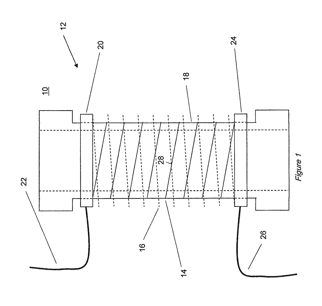
[0033]With reference to FIG. 1, a device 10 according to a first embodiment of the invention comprises coil assembly 12 adapted to carry a current. The coil assembly 12 comprises two coils 14, 16, each comprising a superconducting element, connected in parallel such that each coil 14, 16 carries a portion of the current through the coil assembly 12. The two coils 14, 16 are arranged such that, when the superconducting elements of the coils 14, 16 are each in a superconducting state with a current flowing through the coil assembly 12, the magnetic fields generated by the two coils 14, 16 substantially cancel each other. In this embodiment, this is achieved by arranging the coils 14, 16 as two concentric, preferably coaxial helical coils 14, 16, having a similar diameter and length, connected in parallel and wound in opposition so that the currents in the two coils 14, 16, flow around the axis of the coils in opposite rotational senses. This reduces the magnetic flux density in the re...

second embodiment

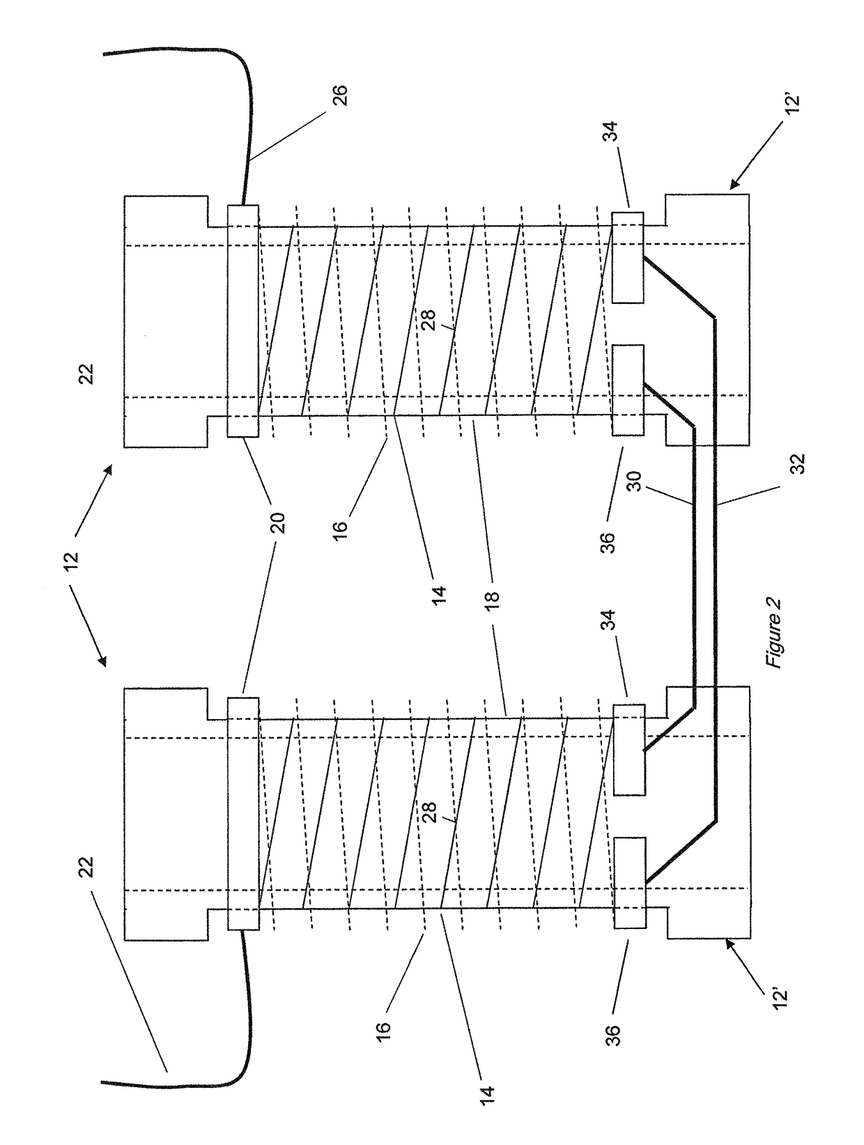
[0043]With reference to FIG. 2, a device 10′ according to a second embodiment of the invention comprises multiple coil assemblies 12′, connected in series, for example to allow the operation of the device 10′ at higher voltage levels. Components which have been described in connection with the first embodiment above are indicated by the same reference numerals. Where it is necessary to connect multiple coil assemblies 12′ in series, the conducting paths through the first and second coils 14, 16 are kept separate throughout the series connected assemblies 12′, by means of connecting all of the first (higher current or lower Ic) coils 14 in series, connecting all of the second (lower current or higher Ic) coils 16 in series and making the parallel connection of the two sets of series connected coils 14, 16 only at the extremities of said sets. This arrangement, applied to two series connected coil assemblies 12′ is shown schematically in FIG. 2. The connections 30, 32 between the coil...

third embodiment

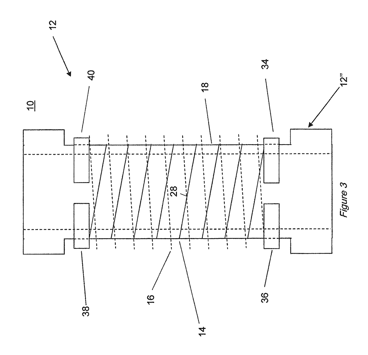
[0044]FIG. 3 shows a further embodiment of a coil assembly 12″ for connection in between the coil assemblies 12′ of the second embodiment where more than two are required to be connected in series. Components which have been described in connection with the first or second embodiments above are indicated by the same reference numerals. A pair of first end electrodes 38, 40 and a pair of second end electrodes 34, 36 allow independent connection to subsequent coil assemblies 12″, 12′ at both ends of the coil assembly 12″. To simplify manufacture, it may be desirable to construct all coil assemblies in this way and to link the end electrodes (e.g. to link end electrodes 34 and 36, or to link end electrodes 38, 40) at the extremities of the two sets of series connected coils, at the point where the external connections 22, 26 are provided.

[0045]Those skilled in the art will appreciate that this method of interconnection is provided to ensure that under any fault conditions including fau...


PUM

PropertyMeasurementUnit
currentaaaaaaaaaa
superconductingaaaaaaaaaa
temperaturesaaaaaaaaaa

Abstract

A device (10) for a current limiter is described, the device (10) comprising: at least one coil assembly (12) adapted to carry a current, the coil assembly (12) comprising: a first coil (14), comprising a first superconducting element, adapted to carry a first portion of said current, and a second coil (16), comprising a second superconducting element, adapted to carry a second portion of said current, wherein said first and second coils (14, 16) are arranged such that, when said first and second superconducting elements are each in a superconducting state and said coil assembly (12) carries said current, a magnetic field generated by said first portion of said current in said first coil (14) is substantially cancelled by a magnetic field generated by said second portion of said current in said second coil (16); and wherein said device is adapted such that, in use, the first superconducting element carries a higher proportion of said current than the second superconducting element. The device may be used in a superconducting fault current limiter to provide a low inductance during normal operation and a rapid and even quench under fault current conditions.

Description

FIELD OF THE INVENTION[0001]The present invention relates to devices for current limiters and current limiters including such devices, and relates particularly but not exclusively to fault current limiters utilising superconducting circuits maintained at a low temperature.BACKGROUND OF THE INVENTION[0002]Fault-current limiters have been implemented using superconducting material to carry the current in an electricity supply network. Such networks normally are expected to carry currents of a few hundred amperes, but if a short-circuit (fault) occurs, the current rises to levels which can be several tens of thousands of amperes. When a fault occurs, the current density in the superconducting material exceeds the critical current density of the material, which ceases to be superconducting and becomes resistive. This process is known as quenching. The presence of resistance in the circuit causes the current to be reduced, or “limited”, reducing the potentially damaging effects of excess...

Claims


Application Information

Patent Timeline
Patent Type & Authority Patents(United States)
IPC IPC(8): H02H9/02H01F6/00H01L39/16
CPCH02H9/023H01L39/16H01F6/00H01F2006/001H10N60/30
Inventor KLAUS, DAVID WILLIAMWILSON, ADRIAN
Owner ROLLS ROYCE PLC
Why Eureka
Try Eureka