Supercharge Your Innovation With Domain-Expert AI Agents!

Energy storage module with DC voltage intermediate circuit

a technology of energy storage module and intermediate circuit, which is applied in the direction of electrical storage system, emergency power supply arrangement, transportation and packaging, etc., can solve the problems of small losses, and achieve the effect of reducing internal electrical losses, reducing waste heat of flywheel storage units, and increasing the efficiency of energy storage modules

Active Publication Date: 2019-01-22
ENRICHMENT TECH CO LTD
View PDF6 Cites 0 Cited by
  • Summary
  • Abstract
  • Description
  • Claims
  • Application Information

AI Technical Summary

Benefits of technology

The invention is a large capacity energy storage system that works well and is safe for the environment. It is easy to operate and can improve local grid quality and also supply non-local power systems. This makes it a useful energy storage system for both purposes.

Problems solved by technology

Using only a large power supply inverter as control system also results in smaller losses than in response to using a plurality of small power supply inverters, for example if all flywheel storage units were connected separately to a power supply system by way of their own power supply inverters.
In addition, an error redundancy, which prevents that, due to the malfunction of a flywheel storage unit, the availability of the energy storage module for its control and systems tasks is significantly impacted in the connected external power supply systems (for example AC grids), is furthermore attained by means of the electrically parallel arrangement of the flywheel storage units.

Method used


Image

  • Energy storage module with DC voltage intermediate circuit
  • Energy storage module with DC voltage intermediate circuit
  • Energy storage module with DC voltage intermediate circuit

Examples


Embodiment Construction

[0036]These and other aspects of the invention will be shown in detail in the illustrations as follows:

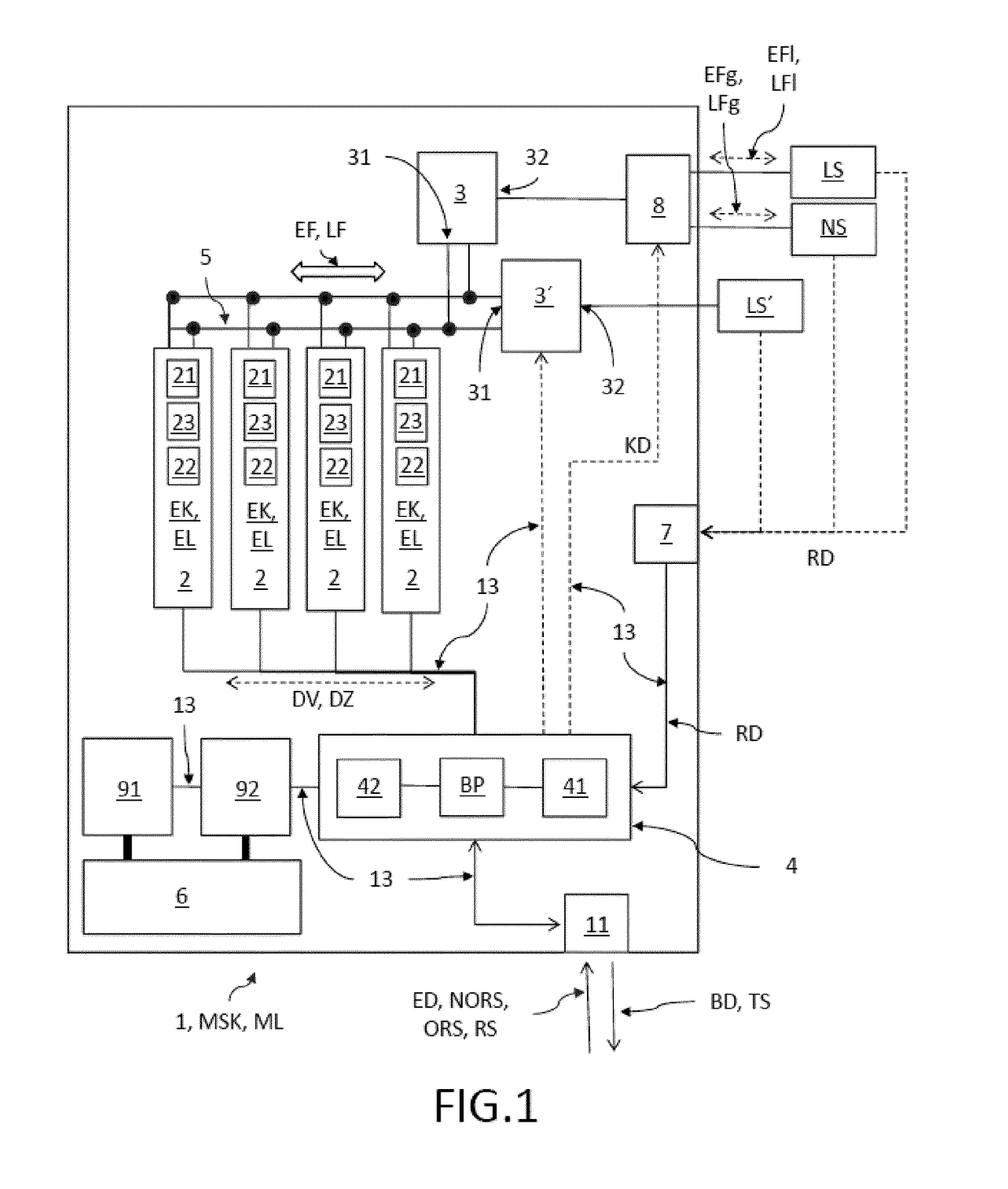
[0037]FIG. 1: an embodiment of the energy storage module according to the invention;

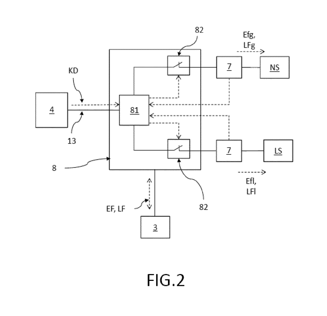
[0038]FIG. 2: an embodiment of the control system comprising control box;

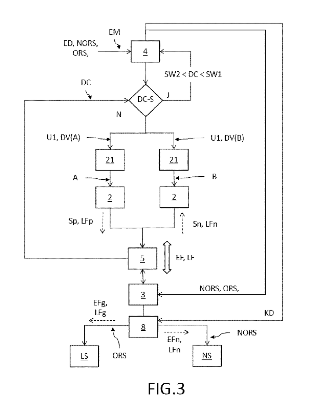
[0039]FIG. 3: an embodiment of the method according to the invention for operating the energy storage module;

[0040]FIG. 4: a further embodiment of the method according to the invention for operating the energy storage module;

DETAILED DESCRIPTION OF THE EXEMPLARY EMBODIMENTS

[0041]FIG. 1 shows an embodiment of the energy storage module 1 according to the invention for reversibly storing electrical energy in the form of mechanical rotation energy, which comprises four flywheel storage units 2 herein, comprising respective unit storage capacities EK and unit outputs EL. This small number was chosen for the sake of clarity in the schematic illustration. For the real application, an energy storage module comprises for example thirty ...


PUM


Abstract

An energy storage module is provided for reversibly storing electrical energy in the form of mechanical rotation energy. The energy storage module comprises a plurality of flywheel storage units, at least one control system and at least one module control unit, wherein the flywheel storage units are connected electrically in parallel by means of a common DC voltage intermediate circuit, and the control system or systems is / are connected to the common DC voltage intermediate circuit by way of the respective output side and to at least one external voltage grid by way of the respective input side, wherein the module control unit is provided for transmitting suitable prespecified torques to the flywheel storage units for emitting or absorbing energy to / from the DC voltage intermediate circuit, and at least one of the control systems is designed to control the DC voltage in the DC voltage intermediate circuit.

Description

RELATED APPLICATIONS[0001]The present invention is a U.S. National Stage under 35 USC 371 patent application, claiming priority to Serial No. PCT / EP2013 / 068724, filed on 10 Sep. 2013; which claims priority from EP 12186479.7, filed 28 Sep. 2012, the entirety of both of which are incorporated herein by reference.FIELD OF THE INVENTION[0002]The invention relates to an energy storage module with DC voltage intermediate circuit and to a method for controlling such an energy storage module.BACKGROUND OF THE INVENTION[0003]The energy for operating a power supply system is supplied by various different types of power plants. Most of the power plants, such as, for example, nuclear power plants, coal-fired power plants, gas-fired power plants, wind energy plants, biogas plants or solar power plants, are hereby only energy generators for feeding energy into to non-local power supply systems. Non-local power supply systems are transmission networks, for example, such as operated in Germany, fo...

Claims


Application Information

Patent Timeline
Patent Type & Authority Patents(United States)
IPC IPC(8): H02J7/00H02J3/30H02J9/08H02J9/00H02J15/00
CPCH02J9/08H02J3/30H02J15/00Y02P90/50Y02E60/16H02J15/007
Inventor VOR DEM ESCHE, ING. RAINERSCHAFER, CHRISTOPHTREPPMANN, ING. CHRISTOPH
Owner ENRICHMENT TECH CO LTD
Features
  • R&D
  • Intellectual Property
  • Life Sciences
  • Materials
  • Tech Scout
  • Unparalleled Data Quality
  • Higher Quality Content
  • 60% Fewer Hallucinations
Learn More