

Actuating device for an electromechanically actuatable vehicle brake
a technology of electromechanical actuation and vehicle brake, which is applied in the direction of braking system, braking, gearing, etc., can solve the problems of a relatively small installation space, limited upward braking or tensioning force which can be generated by the vehicle brake by means of such a known actuating device,
- Summary
- Abstract
- Description
- Claims
- Application Information
AI Technical Summary
Benefits of technology
Problems solved by technology
Method used
Image

Examples
second exemplary embodiment
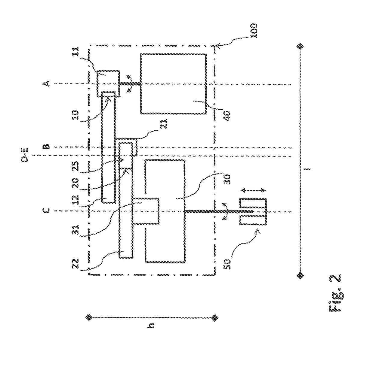
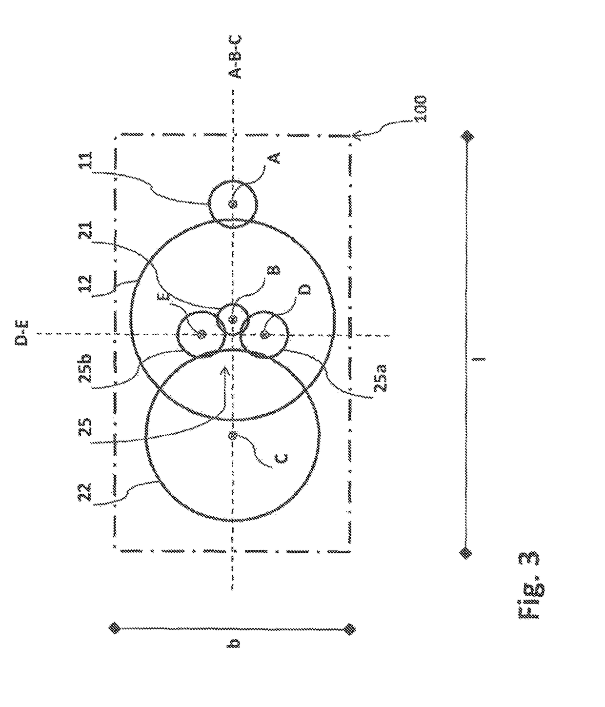
[0057]There will be no more detailed explanation of a third exemplary embodiment of an actuating device according to the invention in which the third stage is embodied as a planetary transmission 30 and in which a further transmission stage is integrated both into the first stage 10 and into the second stage 20 of the transmission unit. This is because this is apparent to a person skilled in the art by combining the inventive actuating device 100 of the first exemplary embodiment according to FIG. 2 and FIG. 3 and the inventive actuating device 110 of the second exemplary embodiment according to FIG. 4 and FIG. 5.
[0058]FIG. 6 is a schematic side view of a fourth exemplary embodiment of an actuating device 130 according to the invention for an electromechanically actuatable vehicle brake. In contrast with the inventive actuating devices 100 and 110 shown in FIG. 2 to FIG. 5, in the transmission unit of the actuating device 130 the first stage 10 and the third stage 30 are each embodi...
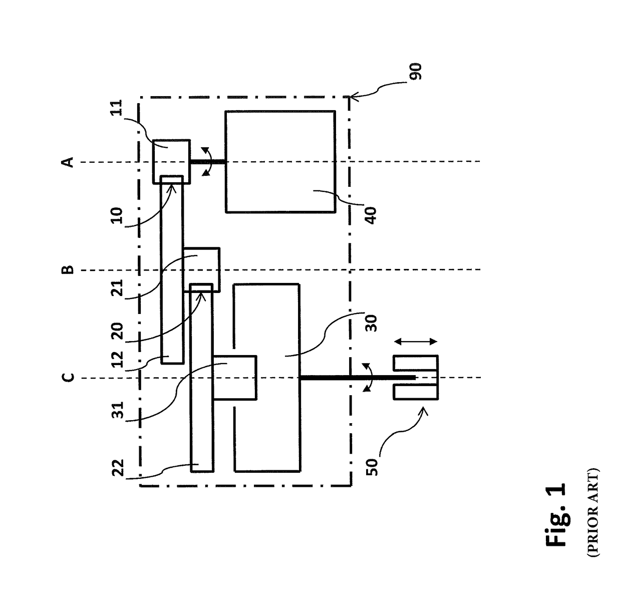
first exemplary embodiment
[0079]There is also no more detailed explanation of a ninth exemplary embodiment of an actuating device according to the invention in which the first stage is embodied as a planetary transmission 10 and in which a further transmission stage is integrated both into the second stage 20 and into the third stage 30 of the transmission unit. This is because it is apparent to a person skilled in the art by combining the inventive actuating device 160 of the seventh exemplary embodiment according to FIG. 8 and the inventive actuating device 100 of the first exemplary embodiment according to FIG. 2 and FIG. 3.
[0080]A person skilled in the art knows that in practice the inventive actuating devices 100, 110, 130 and 160 comprise carrier elements, securing elements, centering elements and the like (not illustrated in more detail), for mounting and positioning the gearwheels 11, 12, 21, 22, 22*, 31, 31*, 32, 24a, 24b, 25a, 25b, 26a and 26b with respect to the rotational axes A, B, C, D, E, F an...
PUM
 Abstract
Description
Claims
Application Information