Power semiconductor device
a technology of power semiconductor and semiconductor chip, which is applied in the direction of semiconductor devices, semiconductor device details, electrical equipment, etc., can solve the problems of limiting the performance of products, large current that reaches several hundred amperes, and time may flow, so as to reduce the transient temperature increase of a power semiconductor chip, increase material cost and device size, and reduce the effect of transient temperature increas
- Summary
- Abstract
- Description
- Claims
- Application Information
AI Technical Summary
Benefits of technology
Problems solved by technology
Method used
Image
Examples
first embodiment
(First Embodiment)
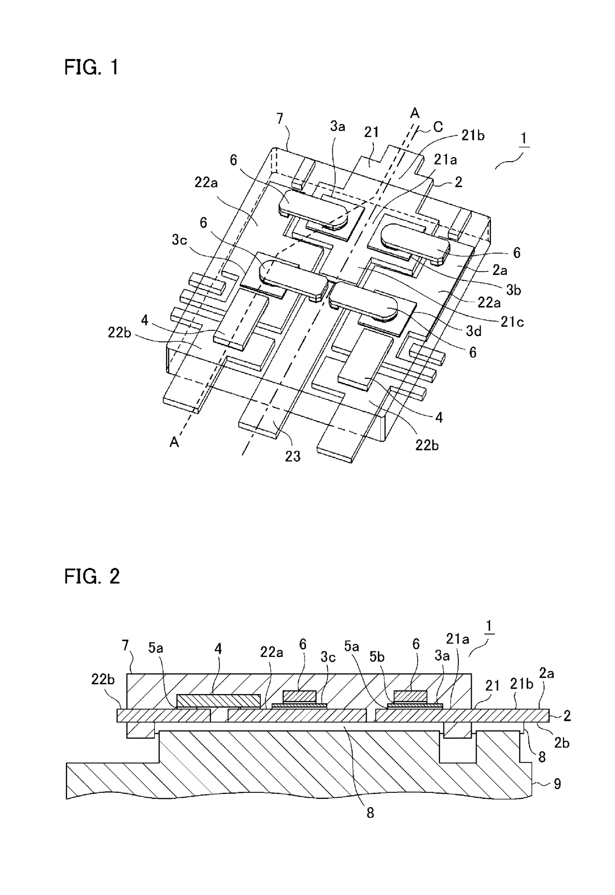
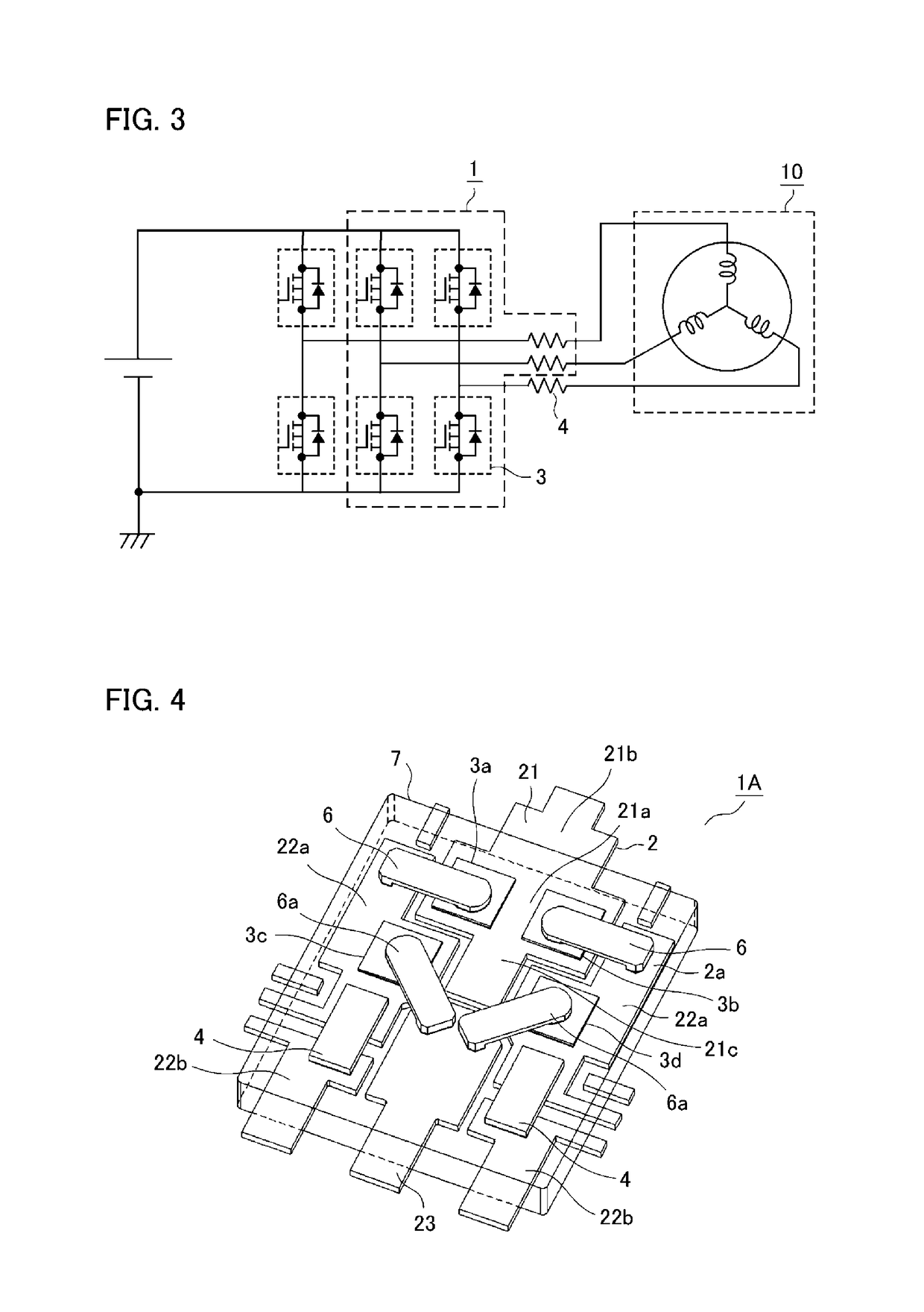
[0022]A power semiconductor device according to a first embodiment of the invention is described below with reference to the drawings. FIG. 1 is an internal perspective schematic view of the power semiconductor device according to the first embodiment. FIG. 2 is a cross-sectional partial view taken along the line A-A in FIG. 1. FIG. 3 is an equivalent circuit diagram of a power conversion circuit including the power semiconductor device according to the first embodiment. Note that, through the drawings, the same or corresponding components are denoted by the same reference numerals.
[0023]A power semiconductor device 1 according to the first embodiment includes: a metallic lead frame 2 shaped in a wiring pattern; switchable upper-side power semiconductor chips 3a, 3b and lower-side power semiconductor chips 3c, 3d (collectively referred to as a power semiconductor chip 3); a current detection resistor 4; conductive joining members 5a, 5b, such as solder; a metallic ...
second embodiment
(Second Embodiment)
[0056]FIG. 4 is an internal perspective schematic view of a power semiconductor device according to a second embodiment of the invention. In a power semiconductor device 1A according to the second embodiment, the lower-side power semiconductor chips 3c, 3d mounted on the first intermediate potential electrode 22a are connected to the N-potential electrode 23 by an inner lead 6a that is placed diagonally with respect to the centerline C of the lead frame 2 (see FIG. 1). The remaining parts are configured in the same way as the first embodiment with their description omitted.
[0057]In the power semiconductor device 1A, the lower-side power semiconductor chips 3c, 3d joined to the first intermediate potential electrode 22a, the N-potential electrode 23, and the inner lead 6a connecting them have each respective circular joining surface pad (not shown). This allows the inner lead 6a to be placed diagonally with respect to the lower-side power semiconductor chips 3c, 3d...
third embodiment
(Third Embodiment)
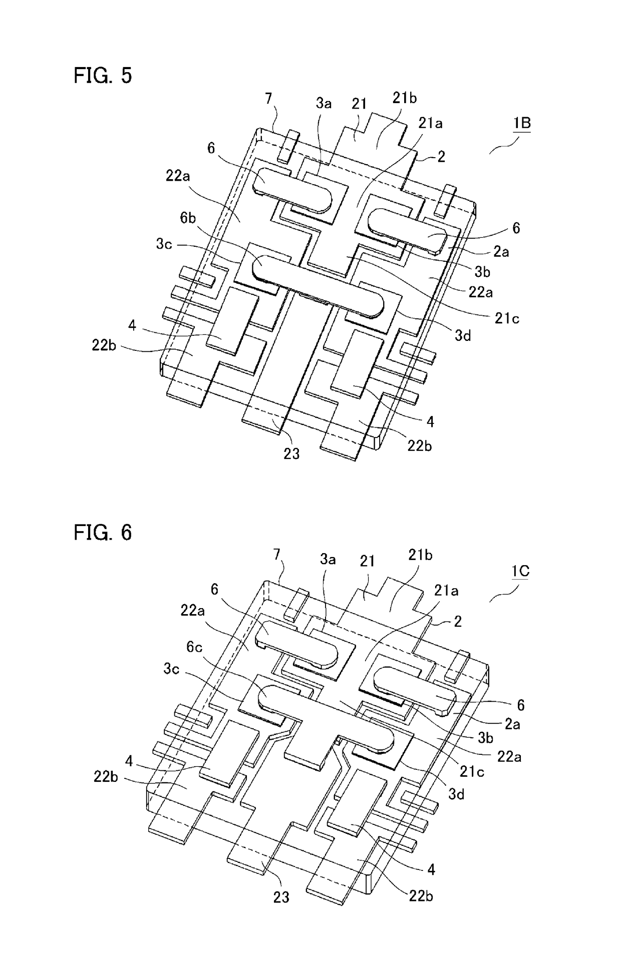
[0059]FIG. 5 is an internal perspective schematic view of a power semiconductor device according to a third embodiment of the invention. In a power semiconductor device 1B according to the third embodiment, the lower-side power semiconductor chips 3c, 3d joined to the first intermediate potential electrodes 22a, respectively, and the N-potential electrode 23 are connected by one straight inner lead 6b. The remaining parts are configured in the same way as the first embodiment with their description omitted.
[0060]The lower-side power semiconductor chips 3c, 3d mounted on the first intermediate potential electrodes 22a, respectively, can be connected by the one straight inner lead 6b with half the workload of using two inner leads, which improves the productivity. Furthermore, the inner lead 6b is fixed at three points, which reduces positional misalignment between the lower-side power semiconductor chips 3c, 3d mounted on the first intermediate potential electrodes ...
PUM
 Abstract
Description
Claims
Application Information
 - R&D
- Intellectual Property
- Life Sciences
- Materials
- Tech Scout
- Unparalleled Data Quality
- Higher Quality Content
- 60% Fewer Hallucinations
Browse by: Latest US Patents, China's latest patents, Technical Efficacy Thesaurus, Application Domain, Technology Topic, Popular Technical Reports.
© 2025 PatSnap. All rights reserved.Legal|Privacy policy|Modern Slavery Act Transparency Statement|Sitemap|About US| Contact US: help@patsnap.com


