Edge finishing for a mesh

a mesh and edge technology, applied in the field of edge finishing for a mesh, can solve the problems of reducing the safety of the edge, and causing a significant safety concern, so as to achieve the effect of increasing safety and little or no reduction of the spacing

Active Publication Date: 2019-02-05
UMC INNOVATION LTD
View PDF24 Cites 0 Cited by
  • Summary
  • Abstract
  • Description
  • Claims
  • Application Information

AI Technical Summary

Benefits of technology

[0019]An edge finishing of this type may have several advantages over prior art finishings, including: providing greater resistance to any force applied to the finishing to pull it apart or undo it; improved safety in that the exposed ends of the pickets are formed into loops having no sharp protrusions; improved stability and rigidity of the finishing as the locked loops are held in place with respect to the mesh; and a consequence of locking the loops together is that the adjacent strands of the first and second pickets may also be held in place.
[0025]An advantage of the arrangement described above is that there may be little or no distortion of the mesh in the vicinity of the edge finishing, and in particular little or no reduction in the spacing between adjacent pickets when the mesh is under tension. This may overcome a problem with prior art finishings where the finishing results in a gap forming at the intersections of the pickets at the edge of the mesh.
[0026]In a preferred embodiment a free end of each picket (which is formed into a loop-end) may be located in the plane of the loop of that picket. An advantage of this arrangement may be increased safety when handling the finishing as the usually sharp picket tail is tucked out of the way inside the smooth surface of the loop.
[0030]In a preferred embodiment the passageway is configured to accept a support wire or cord. This may enable a support wire or cord (or similar) to be threaded through the loops thus holding them all together without creating any distortion of the finishing or the mesh. Such a support may be useful for holding the mesh in shape, to attach the mesh to a post or frame, or for attaching a floatation device if the mesh is to be submerged in water, and so on.
[0032]In a preferred embodiment at least part of the edge finishing is formed using a machine. Those familiar with bending 4 mm wire will appreciate that it requires considerable force to form the pickets into loops. This makes manually forming the edge finish a difficult and strenuous job, particularly as the edge finish becomes more complex. A suitable machine may be able to make the bends, thus saving labour, time and cost in forming the edge finishing. A machine may also produce an edge finishing that is of a consistent standard, rather than the variations that can occur with manually formed edge finishings.

Problems solved by technology

This not only creates a safety issue, but also provides little impediment to the edge of the mesh being unravelled.
While this can be effective in maintaining the integrity of the mesh at the edge, it still creates a significant safety concern as the twisted ends are both rigid and sharp.
This method of edge finishing is no longer allowed to be used for some applications in some countries.
While safer than the twisted finishing, the single knuckle joint can lack the strength to maintain the integrity of the mesh at the edge, and can be pulled apart if sufficient force is applied (for example by being pushed by a large animal).
The knuckle finishing of FIG. 2 can be too weak for this purpose, while the twisted finishing of FIG. 1 can be too dangerous to handle.
The double knuckle edging may be safer than the twisted finishing, but it can still be a hazard if anything catches on the exposed picket tails.
Furthermore, this arrangement can have the disadvantage that the configuration of adjoining U-shaped loops and the manner in which the final knuckles are formed can make forming this double knuckle by machine very difficult.
This form of double knuckle is typically formed manually which can have a number of disadvantages, including a significant increase in the labour, time and cost of producing a mesh with this type of double knuckle finishing.
Furthermore, as the knuckles are formed manually there can be irregularities in the knuckles around the edge of the mesh, which can lead to distortion of the mesh and uneven distribution of the load on the edges of the mesh which can result in high wear / failure of the over loaded edge.
However a more significant issue is that the length of the preformed picket (i.e. the distance between bends in the picket) and the length of the picket end can be insufficient to completely double back over the adjacent picket when completing the first bend and to form the knuckle.
A major issue that is caused by a shortened edge is that additional pickets are required to meet a given specification for a length of mesh.
Additional pickets for a given length of mesh increases the manufacturing cost and also increases the per meter weight of the mesh, requiring additional floats to be provided for mesh fish cages.
Shortening of the edge can also result in a loss of tension in the central portion of the mesh, which in turn can lead to increased rubbing of the pickets at each intersection, thus increasing wear, and removing any surface preparation of the wires (for example antifouling treatment).
Furthermore, the loss of tension can create a situation where a large predator can charge at the un-tensioned section of the mesh and can stun or kill the fish inside.

Method used


Image

  • Edge finishing for a mesh
  • Edge finishing for a mesh
  • Edge finishing for a mesh

Examples


Embodiment Construction

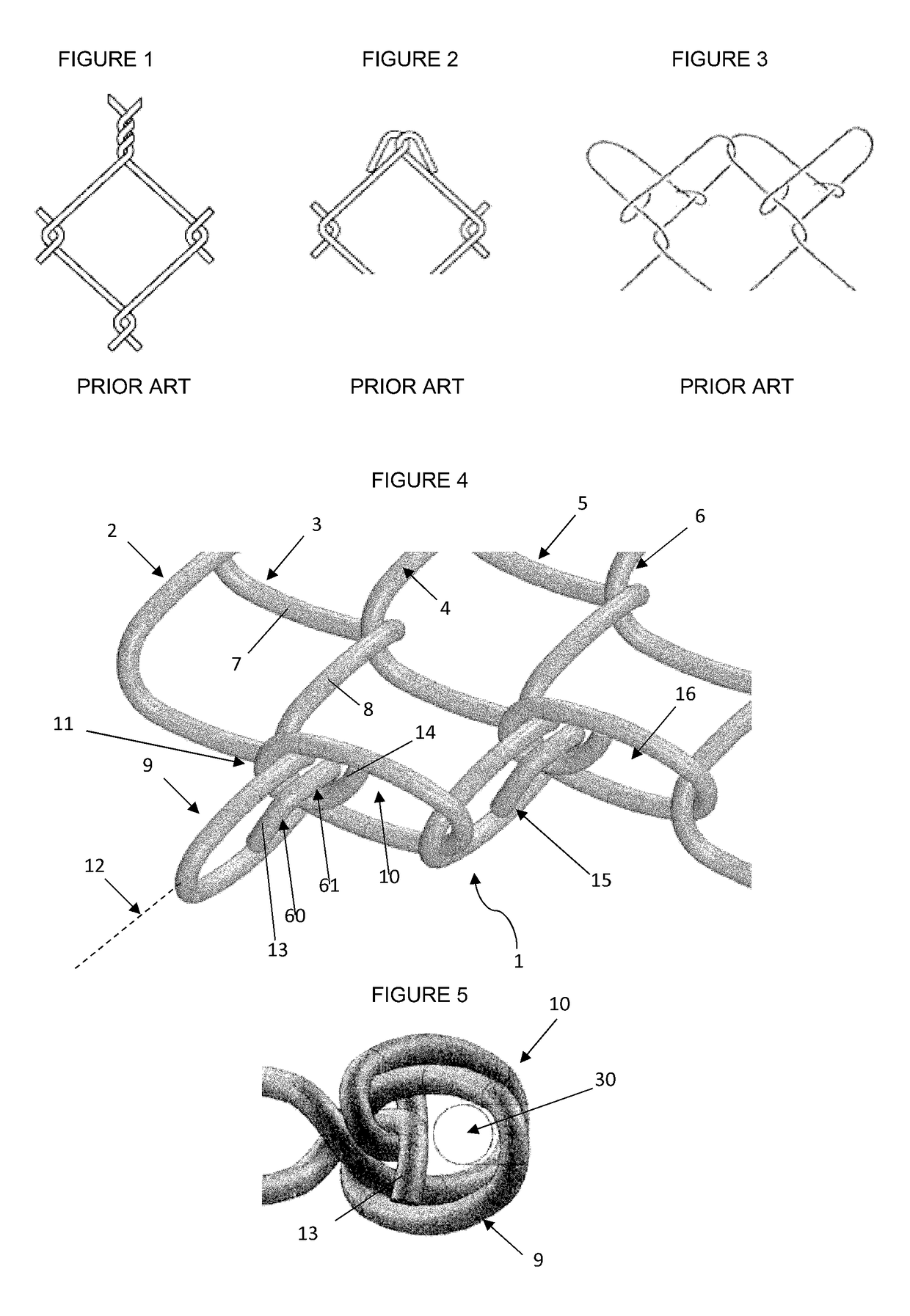
[0069]An edge finishing for a diamond pattern wire mesh according to a preferred embodiment of the present invention is generally indicated by arrow 1 in FIG. 4. The mesh is formed in a diamond pattern (this being the separation of parallel sides of the diamond pattern). The mesh is formed from interlacing pairs of adjacent pickets (2-6) where each picket is in the form of an elongate strand of wire bent at regular intervals into a zig-zag configuration (see for example the adjacent sides (picket end lengths) 7 and 8 of picket 3).

[0070]The edge finishing comprises two interlinked loops, generally indicated by arrows 9 and 10 on the left hand side of FIG. 4, where the first loop 9 is formed from a first picket 2 and the second loop 10 is formed from a second picket 3 (which is adjacent to picket 2). The first loop 9 and the second loop 10 are interlocked together at an intersection 11 of the first picket 2 and the second picket 3.

[0071]The interlocking of loops 9 and 10 is achieved b...


PUM


Abstract

An edge finishing for a mesh formed by interlacing adjacent wire pickets, each picket formed in a zig-zag manner, the edge finishing comprising two interlinked loops where a first loop is formed from a first picket of the adjacent pickets and a second loop is formed from a second picket of the adjacent pickets, wherein the first loop and the second loop are interlocked together, via first and second loop-ends, at an intersection of the first picket and the second picket.

Description

CROSS-REFERENCE TO RELATED APPLICATIONS[0001]This application is a U.S. National Stage of International Patent Application No. PCT / NZ2016 / 050083, filed 20 May 2016, which claims priority to New Zealand Patent Application No. 708418, filed on May 22, 2015 and New Zealand Patent Application No. 720396, filed on May 20, 2016. The disclosure of each application which is incorporated herein by reference in their entirety.STATEMENT OF CORRESPONDING APPLICATIONS[0002]This application is based on the Provisional specification filed in relation to New Zealand Patent Application Number 708418, the entire contents of which are incorporated herein by reference.TECHNICAL FIELD[0003]The invention relates to an edge finishing for a mesh and a method of forming the edge finishing. In particular the edge finishing relates to a wire mesh and a method of forming same for use in aquaculture, although use of the edge finishing for a mesh may have numerous applications, so that use in aquaculture should ...

Claims


Application Information

Patent Timeline
Patent Type & Authority Patents(United States)
IPC IPC(8): B21F27/00B21F27/02A01K3/00B21F27/14A01K75/00A01K61/60
CPCA01K61/60A01K3/00B21F27/005B21F27/14A01K75/00Y02A40/826Y02A40/81
Inventor ULLRICH, MARK WILLIAMTHELNING, NELSON HARTLEYANDERSON, KEVIN MCBRIDE
Owner UMC INNOVATION LTD
Why Eureka
Try Eureka