Liquid crystal display device and manufacturing method thereof

a liquid crystal display and liquid crystal technology, applied in the direction of optics, instruments, transportation and packaging, etc., can solve the problems of reducing the mechanical strength of the film, and the inability to cope with products in the future, and achieve high display contrast, and excellent long-term storage stability.

Active Publication Date: 2019-02-05
JAPAN DISPLAY INC
View PDF13 Cites 3 Cited by
  • Summary
  • Abstract
  • Description
  • Claims
  • Application Information

AI Technical Summary

Benefits of technology

[0014]It is an object of the present invention to provide a liquid crystal display device that can stably provide excellent display characteristics for a long time even in the case where photo-alignment techniques are used and a manufacturing method thereof.
[0024]Moreover, in the liquid crystal display device, the alignment film has a structure in which two types of alignment films are stacked in a two-layer structure formed of a photo-alignable photo-alignment upper layer and a low resistive under layer having a resistivity lower than a resistivity of the photo-alignment upper layer. The specific resistivity of the under layer alignment film is decreased, so that it is possible to eliminate electric charges charged on the alignment film in an early stage, and it is possible to reduce an afterglow phenomenon.
[0035]In the formation, the provision of a strong polarity to the base layer is specifically effective in forming an alignment film having a plurality of types of alignment film layers like the alignment film according to an embodiment of the present invention by only a single coating step. In other words, it is possible to use the effect that the alignment film is a liquid solution uniformly mixed with polyimide structures forming a plurality of types of the alignment film layers immediately after the liquid solution is coated and the liquid solution is naturally separated into two layers based on the difference between the surface free energy to the air layer of the topmost layer and the surface free energy of the base layer in the processes of drying the solvent after the liquid solution is coated.
[0036]However, since the effect of the cleanness of the base layer is lost at a moment at which the base layer contacts the liquid solution containing the solvent, the surface free energy difference is smaller than the surface free energy difference in the state immediately before the liquid solution is coated in the midway point in which the concentration of the liquid solution becomes denser for drying the solvent. When a polar group is generated by surface treatment to provide a strong polarity on the base layer to maintain surface free energy, ozone water cleaning, for example, so that it is possible to maintain the surface free energy difference for a long time, and it is possible to keep the properties that cause the liquid solution to be naturally separated into two layers for a long time. Moreover, for such two-layer separation properties, the polyimide structures used for forming a plurality of types of alignment film layers desirably substantially have phase separation properties.
[0040]According to an aspect of the present invention, it is possible to provide a high quality liquid crystal display device that achieves the mechanical strength of a photo-alignment film and has excellent long-term storage stability, viewing angle characteristics, high display contrast, and less afterglow.

Problems solved by technology

However, ultraviolet rays also work in the inside of the film, for which a long-term structural stability is necessary, and the ultraviolet rays optically degrade the inside of the film, and decrease the mechanical strength of the film.
Thus, the ultraviolet rays affect the display stability of a liquid crystal display device when vibrations, impacts, thermal strain, and the like are externally applied, leading to problems to cope with products in future.

Method used


Image

  • Liquid crystal display device and manufacturing method thereof
  • Liquid crystal display device and manufacturing method thereof
  • Liquid crystal display device and manufacturing method thereof

Examples


first embodiment

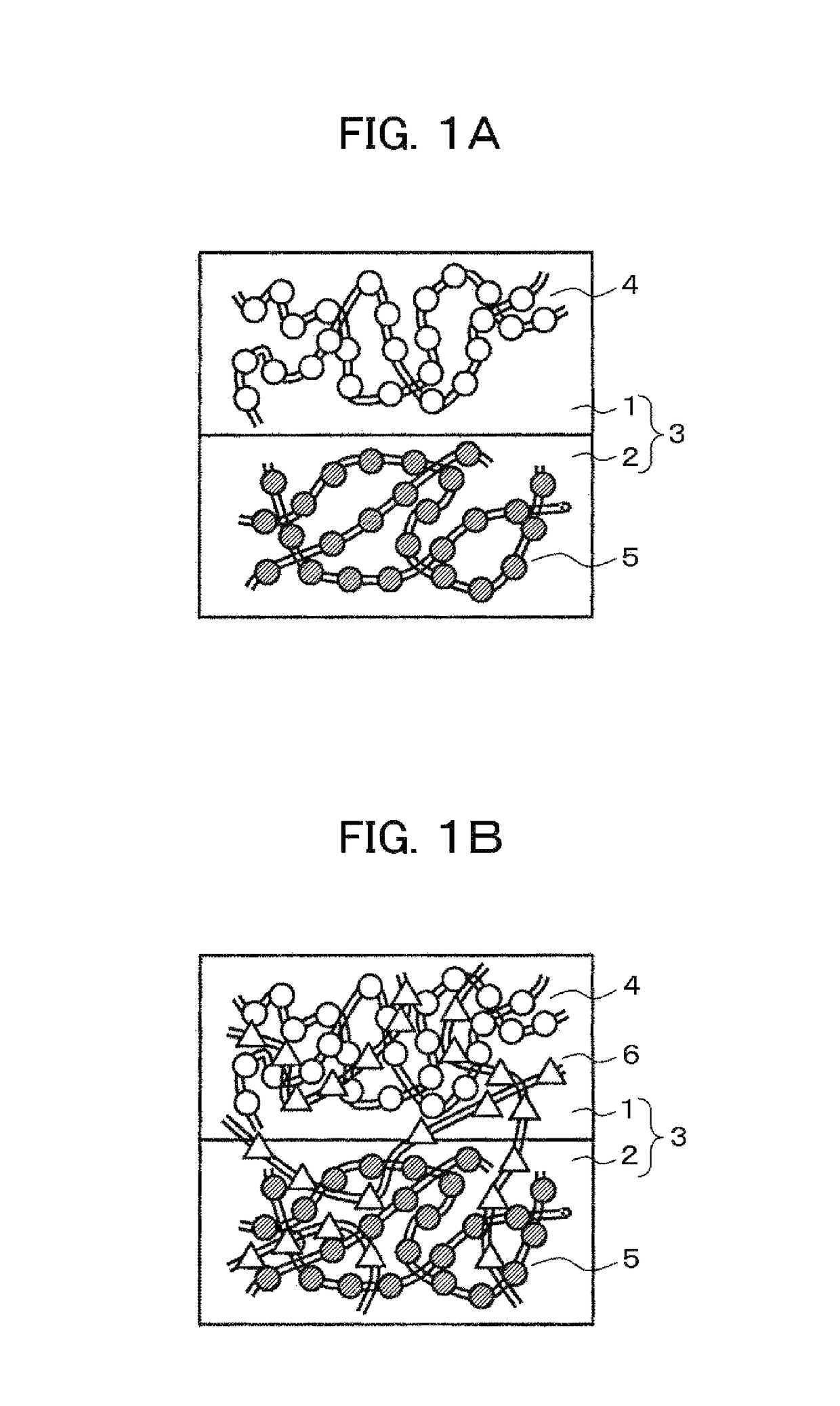
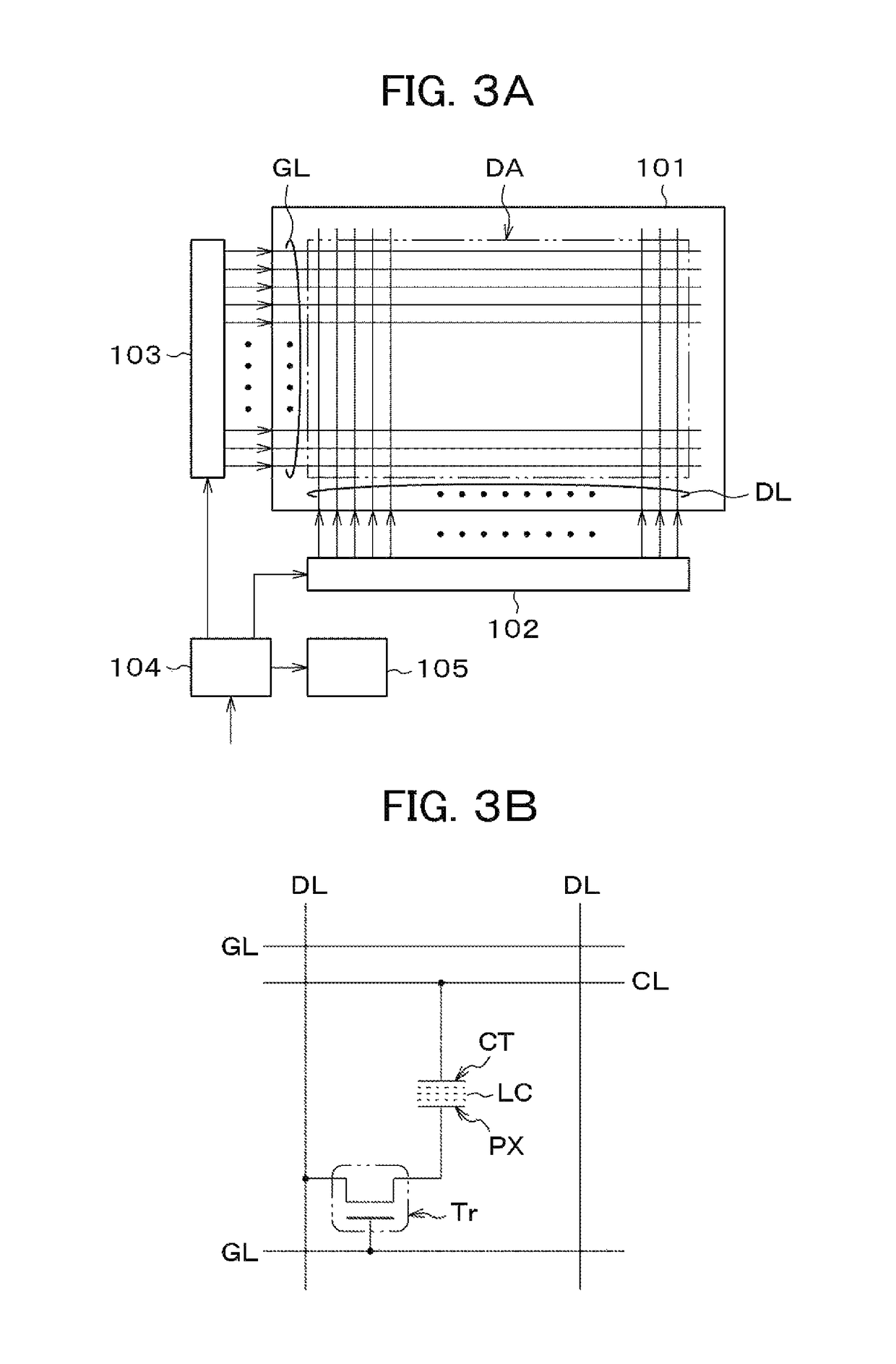
[0102]First, a result of preparing a liquid crystal display device will be described with reference to the drawings and tables, the liquid crystal display device including: a TFT substrate having a pixel electrode and a TFT and formed with an alignment film on a pixel; a counter substrate disposed opposite to the TFT substrate and formed with an alignment film on a top surface on the TFT substrate side; and a liquid crystal sandwiched between the alignment film of the TFT substrate and the alignment film of the counter substrate. In the liquid crystal display device, the alignment film is configured of a first alignment film layer contacting the liquid crystal layer and having at least one kind of polyimide and a second alignment film layer formed below the first alignment film layer and having at least one kind of polyimide, the first alignment film layer is a material that is enabled to provide liquid crystal alignment regulating force by applying polarized light, and the first al...

second embodiment

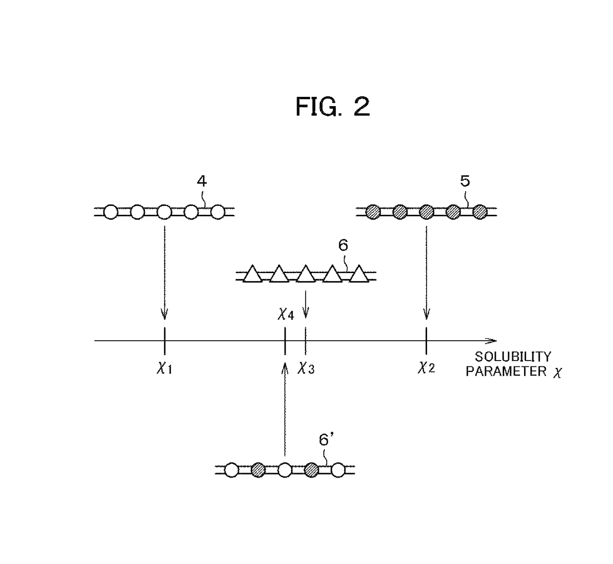
[0113]Next, the result will be described with reference to the drawing and a table that alignment films and liquid crystal display devices were prepared similarly to the procedures of the first embodiment using the common component polymer 6′ composed in another characteristic ratio and the characteristics were compared.

[0114]In other words, the same ones as in the first embodiment were used for the component polymer 4 of the first alignment film layer and the component polymer 5 of the second alignment film layer, and for the common component polymer 6′, one in the characteristic ratio=4:6 was used. The other conditions are the same as the conditions in the first embodiment.

[0115]Table 2 in FIG. 11 is the evaluation results (the anchoring force, the initial film strength, the relative film strength, and the luminance relaxation constant) of the obtained films and IPS liquid crystal display devices using the films. Here, a comparative example was formed in which the mixing ratio of ...

third embodiment

[0118]Next, the result will be described with reference to the drawing and a table that alignment films and liquid crystal display devices were prepared similarly to the procedures of the first embodiment using the common component polymer 6′ composed in another characteristic ratio and the characteristics were compared. In other words, the same ones as in the first embodiment were used for the component polymer 4 of the first alignment film layer and the component polymer 5 of the second alignment film layer, and for the common component polymer 6′, one in the characteristic ratio=6:4 was used. The other conditions are the same as the conditions in the first embodiment.

[0119]Table 3 illustrated in FIG. 12 is the evaluation results (the anchoring force, the initial film strength, the relative film strength, and the luminance relaxation constant) of the obtained films and IPS liquid crystal display devices using the films. Here, a comparative example was formed in which the mixing ra...


PUM

PropertyMeasurementUnit
temperatureaaaaaaaaaa
thicknessaaaaaaaaaa

Abstract

A liquid crystal display device includes: a TFT substrate formed with an alignment film on a pixel; a counter substrate disposed opposite to the TFT substrate and formed with an alignment film on a top surface on the TFT substrate side; and a liquid crystal sandwiched between the TFT substrate and the counter substrate. In the liquid crystal display device, the alignment film is configured of a first alignment film layer contacting the liquid crystal layer and having at least one kind of polyimide and a second alignment film layer formed below the first alignment film layer and having at least one kind of polyimide, the first alignment film layer is a material that is enabled to provide liquid crystal alignment regulating force by applying polarized light, and the first alignment film layer and the second alignment film layer contain a common polyimide structure.

Description

CLAIM OF PRIORITY[0001]The present application claims priority from Japanese Patent Application JP 2014-210116 filed on Oct. 14, 2014, the content of which is hereby incorporated by reference into this application.FIELD OF THE INVENTION[0002]The present invention relates to a high-quality liquid crystal display device that improves viewing angle characteristics and display contrast and a manufacturing method thereof.BACKGROUND OF THE INVENTION[0003]Since liquid crystal display devices have merits such as high display quality, reduced thickness, reduced weight, and low power consumption, the use applications of the devices are expanding, and the devices are used for various use applications including mobile device monitors such as a mobile telephone monitor, digital still camera monitor, personal computer monitor, monitor intended for printing and design, medical monitor, and liquid crystal television. In association with the expansion of these use applications, it is demanded to fur...

Claims


Application Information

Patent Timeline
Patent Type & Authority Patents(United States)
IPC IPC(8): G02F1/1337G02F1/1368G02F1/1341H01L27/12
CPCG02F1/133723G02F1/1341G02F1/133788H01L27/1262G02F1/1368Y10T428/1023C09K2323/027
Inventor IMANISHI, YASUO
Owner JAPAN DISPLAY INC
Why Eureka
Try Eureka