White phosphor converted LED with stable flux output versus temperature

a white phosphor and flux output technology, applied in the field of lighting devices, can solve the problems of unsuitable light sources for automotive applications, and achieve the effects of good luminescent materials for automotive applications, enhanced outcoupling of light, and high brightness sources

Active Publication Date: 2019-02-12
KONINKLJIJKE PHILIPS NV
View PDF6 Cites 0 Cited by
  • Summary
  • Abstract
  • Description
  • Claims
  • Application Information

AI Technical Summary

Benefits of technology

[0020]Hence, in a further embodiment the invention also provides such process, amongst other to provide the herein described ceramic body, such as a process for the production of a ceramic body, comprising a sintering stage comprising sintering a mixture of starting materials, optionally including SiO2, at a temperature in the range of 1500-2000° C. in a first atmosphere to provide a sintered body), followed by an annealing stage comprising an annealing at 1000-1600° C. in a second atmosphere to provide said ceramic body, wherein the first atmosphere differs from the second atmosphere, and wherein the second atmosphere comprises a reducing atmosphere. Hence, the first atmosphere, the atmosphere during at least part of the sintering stage may be reducing (such as including H2) or neutral (such as in an inert gas like N2, or He, etc.). Therefore, in an embodiment the sintering stage is applied in a neutral or oxidizing first atmosphere. As indicated above, especially the starting materials comprise SiO2. It appears that when SiO2 is added as flux material, this may have advantageous effects on the stability of the flux. Further, as known in the art the starting materials may include one or more of carbonate, oxides, etc., of the relevant cations, such as Y, Gd and Al. Further, as indicated above, especially the sintering stage comprises a hot pressing. In this way high quality ceramic bodies may be obtained.
[0021]Further, best materials appear to be obtained when the amount of Gd is limited, and / or when also the amount of cerium is relatively low.
[0023]In a further embodiment, 0.05≤y≤0.2 and 0.0015≤z≤0.003. From all ceramic bodies made, ceramic bodies complying with these conditions especially showed the desired optical behaviour. Further, in an embodiment, 0≤q<1, especially 0≤q≤0.8, or q=0. Further, in an embodiment x=0. When q and x are both substantially zero, good luminescent materials for automotive application may be applied.
[0024]The ceramic body, or especially the garnet luminescent material, is configured to convert at least part of the light source light. In other words, one may say that the light source is radiationally coupled to the light converter, especially the luminescent material. The term “radiationally coupled” especially means that the light source and the luminescent material, here the ceramic body, are associated with each other so that at least part of the radiation emitted by the light source is received by the luminescent material (and at least partly converted into luminescence). The ceramic body may be configured at a non-zero distance from the light source, or may be in physical contact. The former embodiment is sometimes also indicated as vicinity or remote, with the former closer and the latter further away from the light source. Herein, in an embodiment the light source comprises a light emitting surface configured at a distance (d) of equal to or less than 1 mm from the ceramic body. Hence, especially the distance is relatively small, or even zero. Hence, in yet a further embodiment the light source comprises a light emitting surface in physical contact with the ceramic body. In these embodiments also the ceramic body will heat up when the light source gets hotter, and also heat generated in the ceramic body by the down conversion process (absorption of short wavelength light from the light source, and emission of longer wavelength light) is conducted through the light source. All temperatures within the physically connected device are determined by the heat conductivity parameters of the physical parts involved. In case of LEDs, one may e.g. also use the socket temperature, as this temperature is proportional to the temperature of the light emitting surface at a given operating current. The invention especially provides its advantages when the ceramic body is coupled to the temperature as the light emitting surface.
[0025]In a specific embodiment, the lighting device comprises a plurality of said solid state light sources, wherein the ceramic body is an elongated ceramic body having a first face and a second face defining a length (L) of the elongated ceramic body, the elongated ceramic body comprising one or more radiation input faces and a radiation exit window, wherein the second face comprises said radiation exit window, wherein the plurality of solid state light sources are configured to provide blue light source light to the one or more radiation input faces. In this way, a high brightness source may be generated. In a further embodiment, the lighting device may further comprise an optical reflector configured downstream of the first face and configured to reflect light back into the elongated ceramic body, wherein the radiation exit window is configured perpendicular to the one or more radiation input faces. This may further enhance the outcoupling of the light. In yet another embodiment the elongated ceramic body may comprise a geometrical concentration factor, defined as the ratio of the area of the radiation input faces and the area of the radiation exit window, of at least 2. A factor larger than 1, especially 2 or larger, or even much larger, may provide high brightness sources, which may be applied amongst others also for projector purposes or other purposes. Yet, in another embodiment the lighting device may further comprise a collimator configured downstream of the radiation exit window and configured to collimate the converter light.
[0026]As indicated above, one of the applications may be in automotive, such as in head lights of cars, trucks, busses, motors, trains, metros, etc. etc. Hence, in an embodiment the invention also provides an automotive lamp comprising the lighting device as defined herein.

Problems solved by technology

It appeared however that some light sources are not suitable for application in e.g. automotive, as the temperature characteristics were deficient.

Method used


Image

  • White phosphor converted LED with stable flux output versus temperature
  • White phosphor converted LED with stable flux output versus temperature
  • White phosphor converted LED with stable flux output versus temperature

Examples


Embodiment Construction

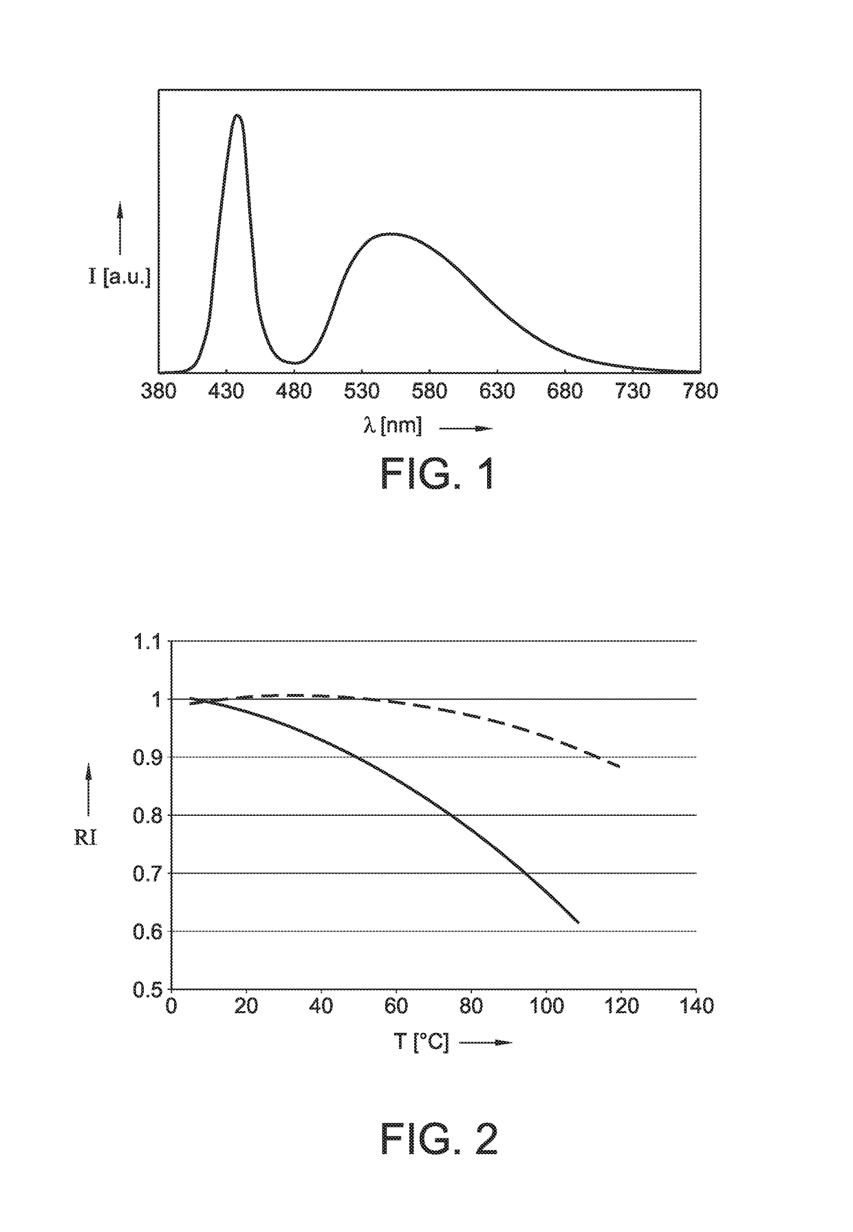
[0056]For some white LED applications, e.g. automotive forward lighting, a stable flux output at different temperatures is required. Blue InGaN LEDs reduce output power with increasing temperature. This invention describes the combination of a blue LED with a yellow emitting phosphor with stable white flux output with varying LED and phosphor temperature, by using a Lumiramic converter which increases QE as a function of temperature (at high blue power input).

[0057]In automotive forward lighting white LEDs are used, made of a blue emitting InGaN LED (430-460 nm peak emission) combined with a yellow emitting garnet phosphor (Y,Gd)3Al5O12 activated with Ce. FIG. 1 shows a typical white emission spectrum. Here the garnet phosphor consists of a Lumiramic converter with a Ce conc. of 0.24% and a Gd concentration of 13% (i.e. (Y0.8676Gd0.13Ce0.0024)3Al5O12. FIG. 1 shows the emission spectrum of a phosphor converted blue LED. Color point is: u′=0.204, v′=0.478 (CIE 1976). The blue peak wav...


PUM


Abstract

The invention provides a lighting device comprising a solid state light source and a ceramic body, wherein the solid state light source is configured to provide blue light source light to the ceramic body, wherein the ceramic body comprises a ceramic material configured to wavelength convert part of the blue light source light into yellow converter light, to provide white lighting device light comprising said blue light source light and said yellow converter light, said white lighting device light having a color point selected from the range of 0.18≤u′≤0.25 and 0.42≤v′≤0.54, and wherein the ceramic material comprises a (Y(1-y-q-z),Gdy,Luq, Cez)3(Al(1-x),Gax)5O12 ceramic material, with 0≤x≤0.6, 0≤y≤0.5, 0≤q<1 and 0.001≤z≤0.06.

Description

CROSS-REFERENCE TO RELATED APPLICATIONS[0001]The present application is a § 371 application of International Application No. PCT / EP 2016 / 053117 filed on Feb. 15, 2016 and titled “WHITE PHOSPHOR CONVERTED LED WITH STABLE FLUX OUTPUT VERSUS TEMPERATURE, ” which claims the benefit of European Patent Application No. 15156087.7 filed on Feb. 23, 2015. International Application No. PCT / EP 2016 / 053117 and European Patent Application No. 15156087.7 are incorporated herein.FIELD OF THE INVENTION[0002]The invention relates to a lighting device, such as for use in automotive applications. The invention further relates to a process for the production of a cerium comprising garnet for use in such lighting device, as well as to the cerium comprising garnet obtainable with such process.BACKGROUND OF THE INVENTION[0003]Luminescent ceramic materials are known in the art. US2004145308, for instance, describes a light source, having at least one LED for emitting a primary radiation and at least one lu...

Claims


Application Information

Patent Timeline
Patent Type & Authority Patents(United States)
IPC IPC(8): H01J1/63F21V8/00H01L33/50F21V9/40
CPCG02B6/0003H01L33/502F21K9/20F21Y2115/10
Inventor BECHTEL, HANS-HELMUTSTEIGELMANN, OLIVER JENSWIECHERT, DETLEF UWEHEIDEMANN, MATTHIAS
Owner KONINKLJIJKE PHILIPS NV
Why Eureka
Try Eureka