Location-determining device in a motor vehicle and information merging method

a technology for determining devices and motor vehicles, applied in navigation instruments, instruments, transportation and packaging, etc., can solve the problems of reduced reception quality, reduced accuracy, and disadvantages of satellite-assisted location determining devices for vehicle applications, so as to promote fast and effective information exchange, speed up the method, and simplify the effect of method

Active Publication Date: 2019-02-19
CONTINENTAL TEVES AG & CO OHG
View PDF18 Cites 0 Cited by
  • Summary
  • Abstract
  • Description
  • Claims
  • Application Information

AI Technical Summary

Benefits of technology

[0011]Preferably, additionally the location calculation module is physically integrated in the housing. This results in the further advantage that the location calculation module also requires neither a separate connection to the vehicle power supply nor a separate connection to the vehicle data bus. This further reduces both the installation involvement and the cost involvement. In addition, the prerequisites are provided for comparatively easy-to-accomplish information fusion for the optical sensor unit and the location determining device, since the location calculation module is therefore also physically arranged in the housing of the optical sensor unit. Additional involvement for the data transmission between the optical sensor unit and the location calculation module which calculates the location information, such as cables or separate bus connections, is not needed.
[0024]On the basis of a further preferred embodiment of the invention, the processed image information is used to determine prevailing reception conditions for the position and time signals, and particularly processing of the position and time signals is matched to the prevailing reception conditions. This allows the received position and time signals to be processed by the location calculation algorithm in a manner which is always correct with the situation and largely matched in optimum fashion. Thus, the image information allows identification of whether the vehicle is in an urban canyon on a densely built-up residential estate and the signal path to a particular number of satellites associated with the global navigation system is interrupted by buildings, for example. It is likewise possible to identify whether the vehicle is on a road with clear visibility from above and there are no interruptions in the signal paths from individual satellites. The matching of the processing of the received position and time signals allows location determination with comparatively greater accuracy and reliability.

Problems solved by technology

The satellite-assisted location determining devices for vehicle applications which are known from the prior art are firstly already subject to disadvantages on account of the known mounting locations for the reception apparatus for the satellite signals.
In the first case, the propagation path for the signal from the satellite to the reception apparatus is disturbed by the vehicle roof, which results in reduced reception quality and hence reduced location accuracy.
In the last three cases, although improved reception quality is available, this is associated with increased installation involvement and likewise increased cost involvement.

Method used


Image

  • Location-determining device in a motor vehicle and information merging method
  • Location-determining device in a motor vehicle and information merging method
  • Location-determining device in a motor vehicle and information merging method

Examples


Embodiment Construction

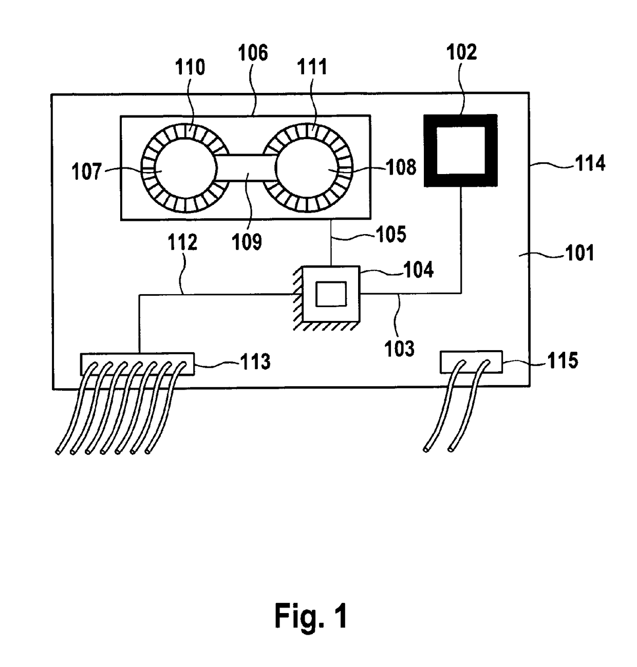
[0029]FIG. 1 schematically shows a possible embodiment of a location determining device 101 according to the invention. Location determining device 101 comprises reception apparatus 102, which is designed to receive position and time signals from a multiplicity of satellites associated with a global navigation system. By way of example, reception apparatus 102 is a GPS antenna. Data line 103 connects reception apparatus 102 to electronic arithmetic unit 104. Electronic arithmetic unit 104 is a fused location calculation module and image processing module. Accordingly, electronic arithmetic unit 104 performs both a location calculation algorithm and an image processing algorithm. As a result, the image information is immediately available for use in the location calculation algorithm, and conversely it is possible for location information to be immediately made available to the image processing algorithm. Particularly the vehicle speed or the distance covered by the vehicle between t...


PUM


Abstract

The invention relates to a location-determining device in a motor vehicle which comprises at least one receiver device for receiving position signals and time signals for a multiplicity of satellites assigned to a global navigation system and a location-calculating module for calculating location information on the basis of received position data and time data. The location-Determining device is distinguished by the fact that the at least one receiver device is structurally integrated into the housing of an optical sensor unit, wherein the housing is arranged in a passenger compartment in a region of an upper edge of a windscreen, and wherein the housing does not have more than a single connection to a vehicle data bus and not more than a single connection to a vehicle energy supply.

Description

CROSS-REFERENCE TO RELATED APPLICATIONS[0001]This application claims priority to German Patent Application No. 10 2010 041 265.1, file Sep. 23, 2010 and PCT / EP2011 / 065428, filed Sep. 7, 2011.FIELD OF THE INVENTION[0002]The invention relates to a location determining device and to an information fusion method.BACKGROUND OF THE INVENTION[0003]The prior art discloses a multiplicity of different mono and stereo camera systems for use as ambient sensors in motor vehicle applications. On account of the diverse new opportunities which such camera systems provide in connection with driver assistance systems, they are becoming increasingly widespread. In this context, stereo camera systems are suitable not only for object identification but also, additionally, for distance determination. Similarly, navigation systems—which are usually designed on the basis of GPS—are also present as standard in more and more current vehicles. These navigation systems use received satellite signals to perform...

Claims


Application Information

Patent Timeline
Patent Type & Authority Patents(United States)
IPC IPC(8): G01S5/14G01C21/00G01S19/35G01S19/45B60R11/04
CPCG01C21/00G01S19/45G01S19/35B60R11/04G01S19/01
Inventor STAHLIN, ULRICH
Owner CONTINENTAL TEVES AG & CO OHG
Why Eureka
Try Eureka