Reconfigurable resonators for chipless RFID applications

a resonator and chipless technology, applied in the field of reconfigurable resonators for chipless rfid applications, can solve the problems of high tag cost, limited use of rfid tags in many applications, and the current inability to use chipless rfid tags for inventory control of low-cost products

Inactive Publication Date: 2019-02-19
KING SAUD UNIVERSITY
View PDF11 Cites 6 Cited by
  • Summary
  • Abstract
  • Description
  • Claims
  • Application Information

AI Technical Summary

Benefits of technology

[0006]When an RFID reader broadcasts an interrogation signal, it is received by the receiving antenna and modulated at the transmission line by coupling to the resonators at different frequencies (referred to as a spectral signature), and then reflected back to the RFID reader through the transmitting antenna. Each resonator is designed to operate within a different range of frequencies. Each resonator may encode bits of information, the number of bits depending on the number of states, K. If there are K−1 adjusting or shorting elements and N resonators, then there are KN possible codes for encoding the tag. Thus, a single resonator circuit can be used for multiple applications by configuring the K−1 adjusting or shorting elements of the N resonators, which is more economical than current chipless RFID tag designs.

Problems solved by technology

However, this limits the use of RFID tags in many applications due to high tag cost compared to item cost.
However, chipless RFID tags are currently not in use for such applications as inventory control for low cost products primarily because of the need for an economical way of encoding more information on a small, passive tag that can be applied to products or packaging, e.g., by printing with conductive ink.

Method used


Image

  • Reconfigurable resonators for chipless RFID applications
  • Reconfigurable resonators for chipless RFID applications
  • Reconfigurable resonators for chipless RFID applications

Examples


Embodiment Construction

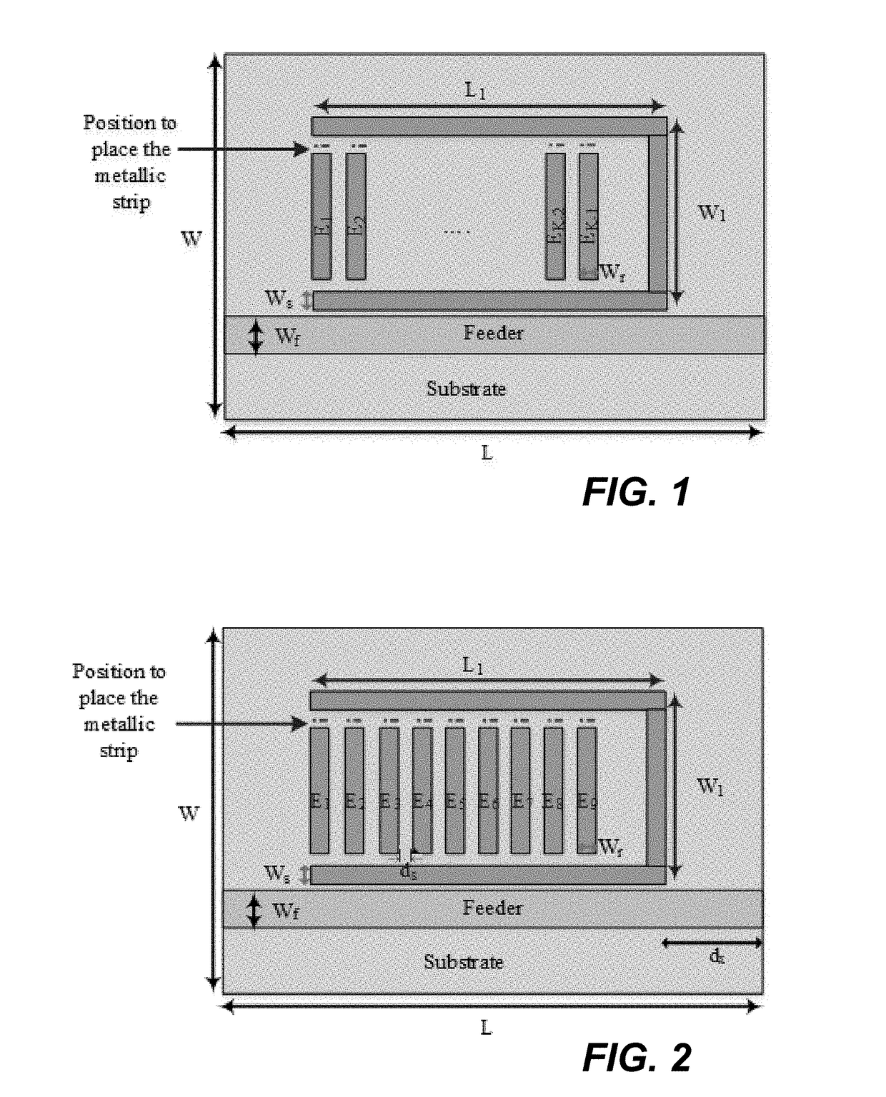
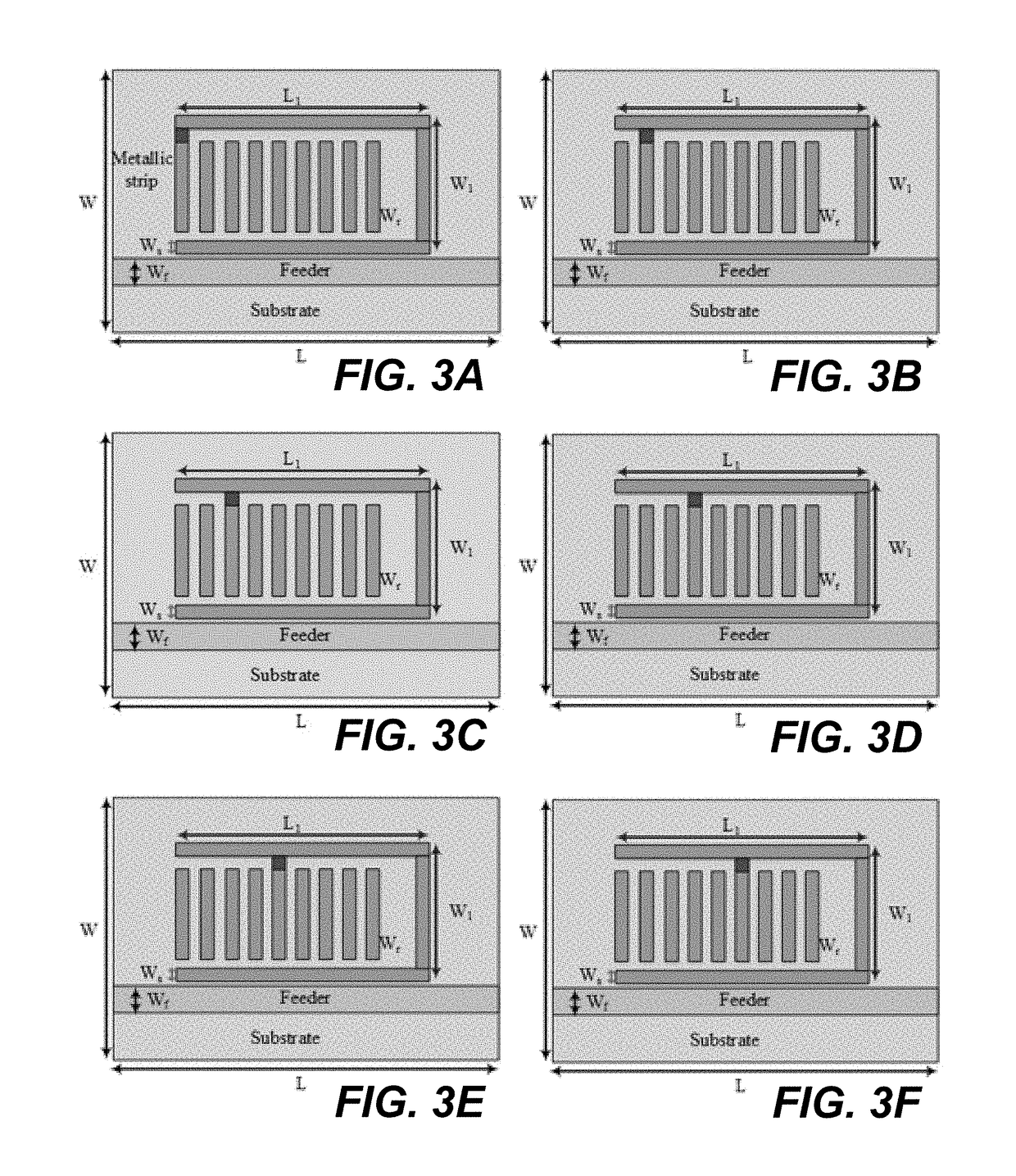
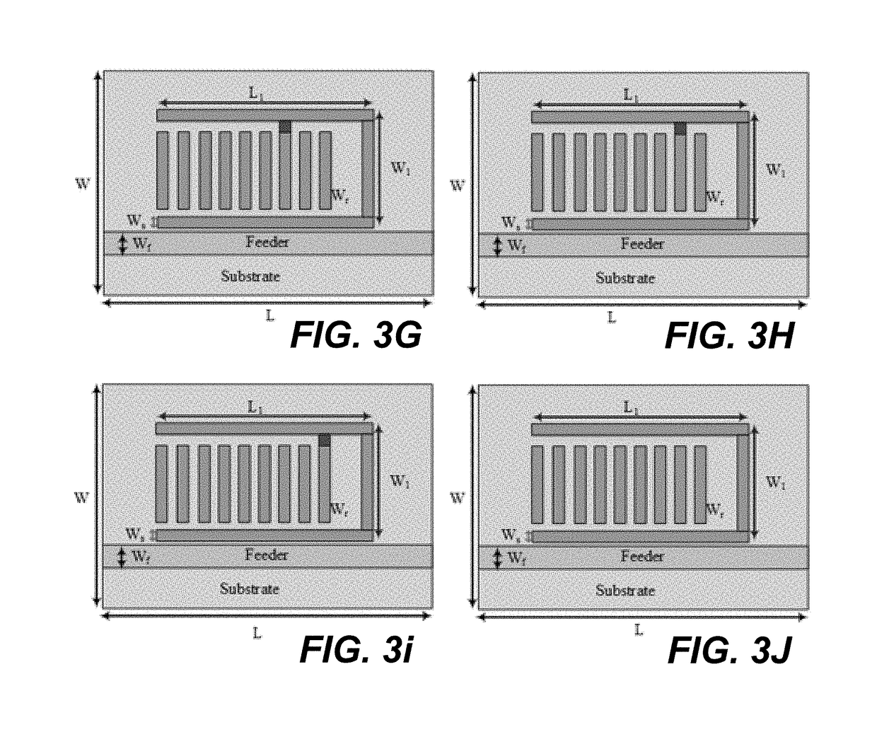
[0019]The reconfigurable resonators for chipless RFID applications provide spiral resonators for a multiple resonator passive RFID transponder tag. Each spiral resonator includes a U-shaped frame of conductive material and has a plurality (K−1) of parallel adjusting or shorting elements disposed between the legs of the U-shaped frame. Each resonator has one leg coupled to a transmission line adapted for connection between a receiving antenna and a transmitting antenna (in some embodiments, a single antenna may be used for both receiving and transmitting), and one of the adjusting or shorting elements may be selectively connected to the opposing leg of the frame to configure the resonator to resonate at one of (K−1) different resonant frequencies (K frequencies if none of the elements are connected) by a short metal jumper strip to change the length of the spiral resonator.

[0020]When an RFID reader broadcasts an interrogation signal, it is received by the receiving antenna and modula...


PUM


Abstract

The reconfigurable resonators for chipless RFID applications provide spiral resonators for a multiple resonator passive RFID transponder tag. Each spiral resonator includes a U-shaped frame of conductive material and has a plurality (K−1) of parallel adjusting or shorting elements disposed between the legs of the U-shaped frame. Each resonator has one leg coupled to a transmission line adapted for connection between a receiving antenna and a transmitting antenna (in some embodiments, a single antenna may be used for both receiving and transmitting), and one of the adjusting or shorting elements may be selectively connected to the opposing leg of the frame to configure the resonator to resonate at one of (K−1) different resonant frequencies (K frequencies if none of the elements are connected) by a short metal jumper strip to change the length of the spiral resonator.

Description

BACKGROUND1. Field[0001]The disclosure of the present patent application relates to passive, resonator-type RFID devices, and particularly to reconfigurable resonators for chipless RFID applications that function without a power storage and without an integrated circuit (IC) chip.2. Description of the Related Art[0002]Researchers are focusing on developing low cost chipless radio frequency identification (RFID) systems. Chipless RFID tag technology has been recently proposed as a promising way to reduce the tag cost. The cost reduction is mainly achieved by eliminating the need of an IC chip, and thus producing fully printable tag structures. The tag cost, in this case, depends on the substrate material, the material size, the technology, and the amount of conductive material used.[0003]RFID technologies have been developed in recent years to overcome barcode limitations, such as low storage capacity, the need for a line-of-sight, small range, and an inability to reprogram. A common...

Claims


Application Information

Patent Timeline
Patent Type & Authority Patents(United States)
IPC IPC(8): G06K19/077G01S13/75H01P7/08G06K7/10H01P1/203
CPCH01P1/20363G06K7/10356H01P7/082G06K19/07773G01S13/753G06K19/0775G06K19/0672G06K19/0677
Inventor ABDULKAWI, WAZIE MOHAMMED AHMEDSHETA, ABDEL FATTAH AHMED
Owner KING SAUD UNIVERSITY
Why Eureka
Try Eureka