Laser machining apparatus with adaptive mirror

a technology of mirror and machining machine, which is applied in the field of laser machining, can solve the problems of affecting cutting procedures, affecting the position and affecting the quality of the finished product, so as to achieve better positioning and shape of the focal spo

Active Publication Date: 2019-02-26
LT ULTRA PRECISION TECH
View PDF35 Cites 0 Cited by
  • Summary
  • Abstract
  • Description
  • Claims
  • Application Information

AI Technical Summary

Benefits of technology

[0023]It is the object of the invention to specify a laser machining apparatus with which the position and shape of the focal spot can be stabilised better.
[0030]By virtue of the locally varying thickness of the mirror substrate of the first adaptive mirror, said substrate opposes a change in the internal pressure with a locally differing resistance. Whereas, for example, a plane mirror substrate of constant thickness supported by a single-valued bearing deforms approximately spherically when the internal pressure increases, in the case of adjustment of a varying thickness profile—even in the case of the three-valued bearing of the substrate—arbitrary deformations can be generated within wide limits by a change in the internal pressure. With such deformations the complex imaging errors that are brought about by thermally induced deformations of optical elements in the focusing optics can generally be compensated better than is possible with mirror substrates of constant thickness. The axial position and, above all, also the shape of the focal spot can consequently be stabilised better during operation of the laser machining apparatus.
[0038]In order to be able to drive the two adaptive mirrors, it is favourable if the laser machining apparatus exhibits a measuring device for measuring changes in the focal length of focusing optics contained in the machining head. The measuring device has been set up to direct a first measuring-light bundle and a second measuring-light bundle onto differing regions of an optical surface of the focusing optics, and to evaluate them independently of one another. The regions onto which the measuring-light bundles are directed may in this case have counterparts in the two adaptive mirrors. Given suitable choice of the regions on the optical surface of the focusing optics, a very simple drive of the adaptive mirrors can be achieved, by an adaptive mirror being assigned to each measuring-light bundle. In the simplest case, the measuring signals corresponding to a measuring-light bundle are converted directly, via a simple (where appropriate, even linear) relationship, into control signals for the adaptive mirror in question.

Problems solved by technology

The contamination may, in particular, be caused by splashes of material arising at the machining point or by smoke.
Particularly when the focusing optics contain lenses and other refractive optical elements such as protective discs, the unavoidable residual absorption in the lens materials that are used has the result that the elements heat up.
By virtue of the unintended displacement of the focal spot, the workpieces may no longer be machined in the desired manner.
If the workpiece is located outside the focal spot, the requisite energy densities for fusing metals, for example, are no longer attained, leading to the interruption of cutting procedures and, in the case of welding, to seam defects.
However, as a consequence of the strong emissions of light in the region of interaction with the laser radiation it is difficult to register, unambiguously and in real time, changes of position of the focal spot with the requisite accuracy and independently of the machining process, and thereby to avoid machining defects.
As in the case of lenses, the heating of the reflecting coating leads to a detuning of the layered system, which results in an increased absorption.
Besides the axial displacement of the focal spot, the high-energy laser radiation can also induce other imaging errors in the optical elements of the focusing optics.
Such imaging errors may lead to a blurring of the focal spot, which likewise has a disadvantageous effect on the quality of the machining.
A disadvantageous aspect of this known measuring arrangement is that intense retroreflections from the workpiece can likewise, by virtue of repeated retroreflection on the input-side converging lens, get onto the light sensor and thereby falsify the results of measurement.
In addition, the measuring device requires a relatively large additional construction space, although it is not capable of registering all the optical elements of the focusing optics.
Since, however, light is also reflected from the workpiece to be machined, it is difficult to detect the weak retroreflection of said optical element among the large number of other reflections.
A deformation of an adaptive mirror with the aid of piezoelectric elements, such as the aforementioned JP H02-204701 A discloses, is, however, relatively complex.
However, it has become evident that with adaptive mirrors of such a type the thermally induced changes in the focal spot as regards its axial position and shape can only be compensated inadequately.
By virtue of the deformation of the adaptive mirror, the axial position of the focal spot can indeed be kept constant, but large imaging errors have to be accepted.
The focal spot is then frequently blurred in the lateral and axial directions in such a way that losses of quality may occur in the course of laser machining.

Method used


Image

  • Laser machining apparatus with adaptive mirror
  • Laser machining apparatus with adaptive mirror
  • Laser machining apparatus with adaptive mirror

Examples


Embodiment Construction

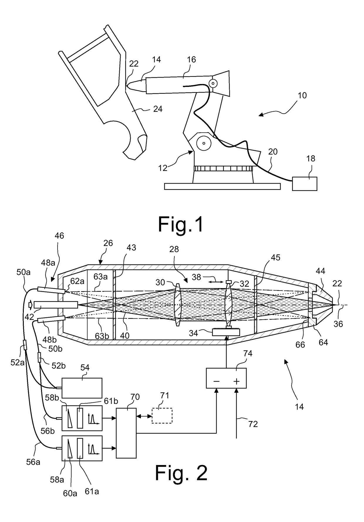
[0066]FIG. 1 shows, in a side view, a laser machining apparatus 10 with a robot 12 and with a machining head 14 according to the invention, which has been fastened to a mobile arm 16 of the robot 12.

[0067]The laser machining apparatus 10 includes, in addition, a laser radiation source 18, which in the embodiment that is represented takes the form of a Nd:YAG laser, disk laser or fibre laser. The laser radiation generated by the laser radiation source 18 is fed via an optical fibre 20 to the machining head 14 and is focused by the latter in a focal spot 22. The arm 16 of the robot 12 is positioned in relation to a workpiece 24 in such a way that the focal spot 22 is located at the desired location on the workpiece 24 and the latter can be machined by welding, severing, or in another way.

[0068]Of course, other lasers also enter into consideration by way of laser radiation source 18, for example CO2 lasers, the radiation of which, however, is generally fed to the machining head 14 not ...


PUM

PropertyMeasurementUnit
diameteraaaaaaaaaa
diameteraaaaaaaaaa
focal lengthaaaaaaaaaa

Abstract

A laser machining apparatus comprises a laser radiation source that generates laser radiation. A first and a second adaptive mirror are provided each having a pressure chamber connected to a pressure source and a mirror substrate that bounds the pressure chamber. An internal pressure in the pressure chamber can be changed with the aid of the pressure source in such a way that the mirror substrate deforms if the internal pressure in the pressure chamber changes. The mirror substrate of the first adaptive mirror has a thickness which varies at least within a region of the mirror substrate that bounds the pressure chamber. The mirror substrate of the second adaptive mirror has a thickness which is constant over the entire region over which the mirror substrate is deformable.

Description

CROSS-REFERENCE TO RELATED APPLICATIONS[0001]This application claims benefit of German patent application Ser. No. 102013008647.7 filed May 21, 2013. The full disclosure of this earlier application is incorporated herein by reference.BACKGROUND OF THE INVENTION[0002]1. Field of the Invention[0003]The invention relates to a laser machining apparatus with which workpieces can be welded, cut, or machined in some other way and which contains an adaptive mirror. The invention further relates to a process for compensating displacements of a focal spot in such a laser machining apparatus.[0004]2. Description of Related Art[0005]Laser machining apparatuses ordinarily include a laser radiation source which may be, for example, a Nd:YAG laser, a fibre laser, a disk laser or a CO2 laser. A laser machining apparatus further includes a machining head, which focuses the laser radiation generated by the laser radiation source in a focal spot, and a beam-feeding device which feeds the laser radiati...

Claims


Application Information

Patent Timeline
Patent Type & Authority Patents(United States)
IPC IPC(8): B23K26/06B23K26/046B23K26/03
CPCB23K26/032B23K26/0643B23K26/046
Inventor JURCA, MARIUS
Owner LT ULTRA PRECISION TECH
Why Eureka
Try Eureka