Supercharge Your Innovation With Domain-Expert AI Agents!

Gas turbine efficiency and power augmentation improvements utilizing heated compressed air

a technology of compressed air and gas turbines, which is applied in the direction of steam engine plants, machines/engines, mechanical equipment, etc., can solve the problems of over-the-counter steam pipe heating process, high rate of steam pipe heating, and high cost, so as to reduce eliminate the chance of water formation

Active Publication Date: 2019-02-26
POWERPHASE
View PDF58 Cites 3 Cited by
  • Summary
  • Abstract
  • Description
  • Claims
  • Application Information

AI Technical Summary

Benefits of technology

The present invention provides methods and systems to prevent water formation during steam injection start-up in gas turbine systems. This is achieved by bleeding air from either the steam injection site or an external source of hot compressed air to preheat the steam injection lines. This results in a more efficient use of steam, reducing plant steam output while increasing plant electrical power output.

Problems solved by technology

This heating process for the steam pipes typically takes approximately thirty minutes.
Since the flow rates are extremely low, as water is typically not desired to be injected through a steam injection system into the gas turbine, this process typically takes in excess of thirty minutes to complete.
Most cogen plants supply both electricity and steam to the steam host and sometimes the steam requirement and power requirement are not optimally balanced, so the cogen plant has to continuously optimize and balance the steam production and gas turbine output to try to meet the steam host's demand.
This is a significant challenge, and as a result, there are periods when excess steam is produced as a result of the power requirement that cannot be avoided, and in these cases, the cogen process loses efficiency.
Steam injection power augmentation systems are not typically deployed to meet short term spot market demands because they can take too long to come online and be available.
For example, if there is a spike in power demand that is not expected to last long, then the steam injection power augmentation system is not advantageous to use.
Additionally, steam injection systems are not considered optimal for fast-acting regulation devices due to their slow start-up speed.
As a result, it takes about thirty minutes for the steam injection system to preheat to a desired operating temperature.
Some steam injection systems do not have the steam vent valve 616 and therefore they can take even longer to preheat because of the sensitivity to injecting water into the gas turbine as the steam injection system is started up.

Method used


Image

  • Gas turbine efficiency and power augmentation improvements utilizing heated compressed air
  • Gas turbine efficiency and power augmentation improvements utilizing heated compressed air
  • Gas turbine efficiency and power augmentation improvements utilizing heated compressed air

Examples


Embodiment Construction

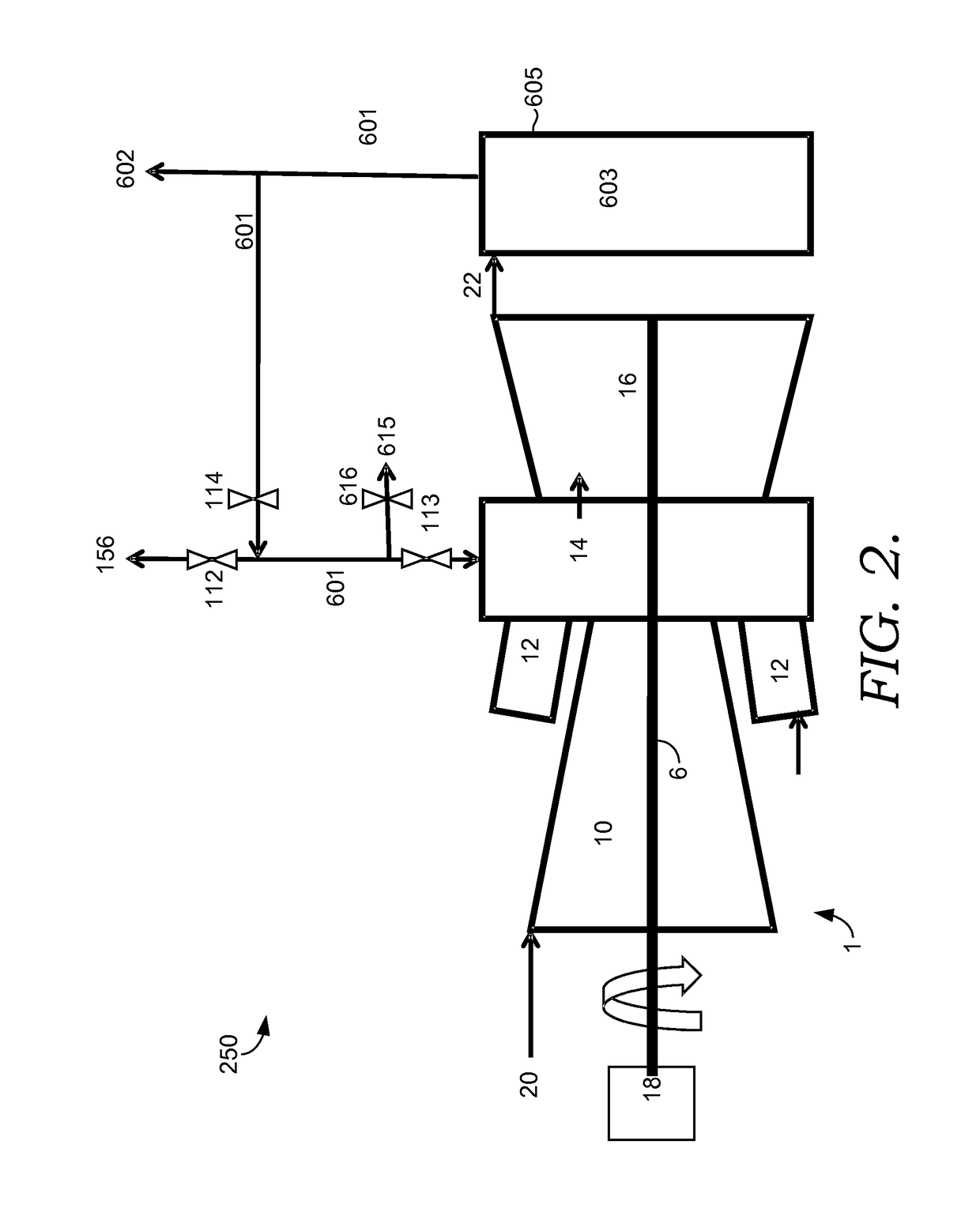
[0023]The present invention is disclosed in FIGS. 2-5. An aspect common to all embodiments of the present invention is an air vent valve 112 positioned near the source of the steam injection, typically very close to the steam injection valve 114. Before steam injection is initiated, the air vent valve 112 is opened to allow air to flow through the steam injection piping, towards the steam source, and discharged into the atmosphere 156. This allows the steam injection piping to be pre-heated to increase the speed that power augmentation with the steam injection system can be started. Various embodiments for heating the steam pipes are discussed herein.

[0024]Typically, steam injection takes at least thirty minutes to initiate and achieve a desired steam injection level. With the steam system pre-heated, the steam injection system can be brought to full flow in less than three minutes. This same air bleed system can be used to purge the steam injection lines when the steam injection pr...


PUM


Abstract

The present invention discloses a novel apparatus and methods for augmenting the power of a gas turbine engine, improving gas turbine engine operation, and reducing the response time necessary to meet changing demands of a power plant. Improvements in power augmentation and engine operation include systems and methods for preheating a steam injection system.

Description

CROSS-REFERENCE TO RELATED APPLICATIONS[0001]None.TECHNICAL FIELD[0002]The invention relates generally to gas turbine engine power systems incorporating a power augmentation system. More specifically, improvements relating to steam power augmentation are provided.BACKGROUND OF THE INVENTION[0003]Currently, many gas turbine engines operating at power plants utilize steam injection systems as a low-cost form of power augmentation. Typically steam injection is considered a relatively constant process because the start-up time and shut-down time of the steam injection system is typically on the order of thirty to sixty minutes.[0004]Some steam injection systems of the prior art have a steam bleed near the injection point so that the steam can be used to heat the steam injection pipes. As steam injection is initiated through cold pipes, the hot steam condenses and forms water which is vented through the steam vent. Steam flow is gradually increased until the pipes are sufficiently heated...

Claims


Application Information

Patent Timeline
Patent Type & Authority Patents(United States)
IPC IPC(8): F02C3/30F01K23/10F01K7/02F01K21/04F02C6/18F02C7/143
CPCF01K23/101F01K7/02F01K21/047F01K23/10F02C3/305F02C6/18F02C7/1435F02C3/30Y02E20/16F05D2260/2322Y02E20/14
Inventor KRAFT, ROBERT J.AUERBACH, SCOTT
Owner POWERPHASE
Features
  • R&D
  • Intellectual Property
  • Life Sciences
  • Materials
  • Tech Scout
  • Unparalleled Data Quality
  • Higher Quality Content
  • 60% Fewer Hallucinations
Learn More