Gear device
a gear device and gear technology, applied in the direction of gearing, gearing details, hoisting equipment, etc., can solve the problems of degrading the durability of the gear device, achieve the effect of reducing the force, reducing the magnitude of the thrust force, and reducing the thrust force generated in the second gear
- Summary
- Abstract
- Description
- Claims
- Application Information
AI Technical Summary
Benefits of technology
Problems solved by technology
Method used
Image
Examples
first embodiment
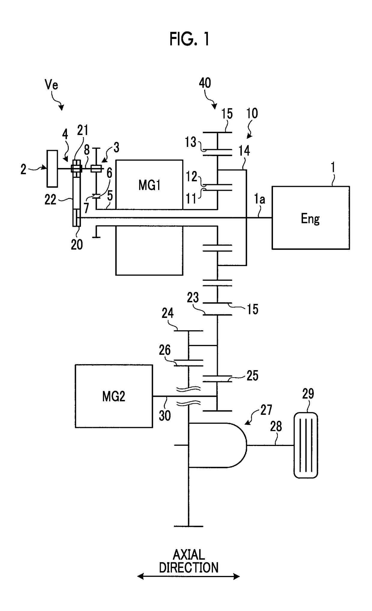
[0031]First, a vehicle in which a gear device according to a first embodiment of the present disclosure is mounted will be described. FIG. 1 is a schematic view showing a main part of a hybrid vehicle according to the first embodiment. In the following description, a gear is a mechanical element including teeth that performs transmission of power. A gear is a concept including a wheel in which a row of teeth that performs transmission of power.
[0032]As shown in FIG. 1, a hybrid vehicle (HV vehicle) Ve includes a first motor MG1, a second motor MG2, an engine 1, an oil pump 2, a first one-way clutch 3, a second one-way clutch 4, and a gear device 40 including a planetary gear mechanism 10. A power transmission device of the HV vehicle Ve includes the planetary gear mechanism 10, the first motor MG1, the second motor MG2, a counter drive gear 15, a counter driven gear 23, a drive pinion gear 24, a reduction gear 25, a differential ring gear 26, and a differential mechanism 27.
[0033]Th...
first modification example
[0068]Next, a first modification example of the gear device according to the first embodiment will be described. FIG. 6 is a sectional view showing a gear device according to the first modification example in the first embodiment.
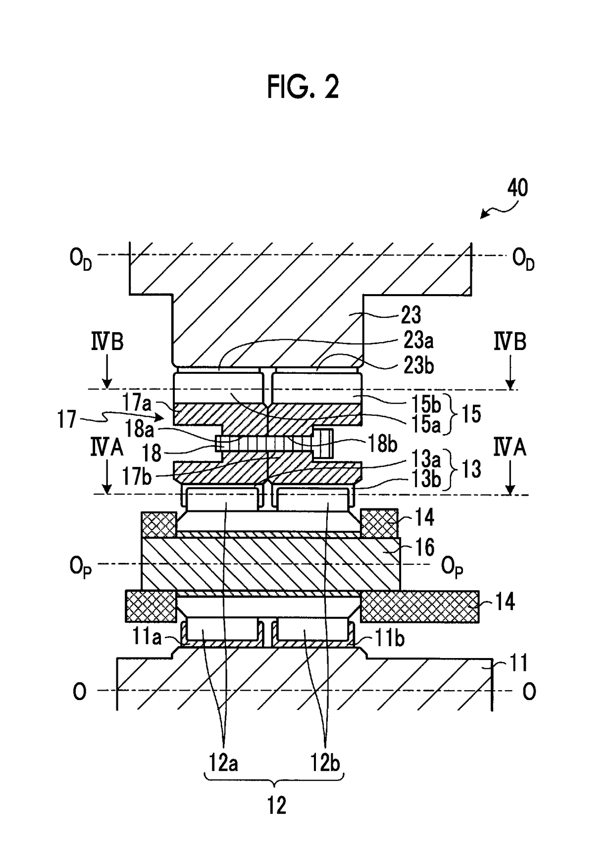
[0069]As shown in FIG. 6, in a gear device 50 according to the first modification example, unlike the first embodiment, a cylindrical ring-shaped gear 51 is formed integrally. That is, on the inner circumference of the ring-shaped gear 51, the left-hand first inner circumferential helical teeth 13a and the right-hand second inner circumferential helical teeth 13b are coaxially formed adjacent to each other. Similarly, on the outer circumference of the ring-shaped gear 51, the left-hand first outer circumferential helical teeth 15a and the right-hand second outer circumferential helical teeth 15b are coaxially formed adjacent to each other. The ring-shaped gear 51 can be formed, for example, by bonding the first ring-shaped gear 17a and the second ring-shape...
second modification example
[0071]Next, a second modification example of the gear device according to the first embodiment will be described. FIG. 7 is a sectional view showing a gear device according to the second modification example in the first embodiment.
[0072]As shown in FIG. 7, in a gear device 60 according to the second modification example, a ring-shaped gear 61 is constituted of a first ring-shaped gear 61a and a second ring-shaped gear 61b that have a hollow cylindrical shape and are substantially symmetrical to the surface perpendicular to the rotation axis O. Internal teeth of the first ring-shaped gear 61a are constituted of the left-hand first inner circumferential helical teeth 13a that mesh with the helical teeth 12a. Internal teeth of the second ring-shaped gear 61b are constituted of the right-hand second inner circumferential helical teeth 13b that mesh with the helical teeth 12b. With this, internal teeth of the ring-shaped gear 61 are constituted of double helical teeth in which the first...
PUM
 Abstract
Description
Claims
Application Information
 - R&D
- Intellectual Property
- Life Sciences
- Materials
- Tech Scout
- Unparalleled Data Quality
- Higher Quality Content
- 60% Fewer Hallucinations
Browse by: Latest US Patents, China's latest patents, Technical Efficacy Thesaurus, Application Domain, Technology Topic, Popular Technical Reports.
© 2025 PatSnap. All rights reserved.Legal|Privacy policy|Modern Slavery Act Transparency Statement|Sitemap|About US| Contact US: help@patsnap.com


