Stepwise operating parallel type small hydro power generation system having fixed flow path

a technology of power generation system and stepwise operation, which is applied in the direction of electric generator control, renewable energy generation, greenhouse gas reduction, etc., can solve the problems of power generator overloaded, water turbine damage, and inability to solve problems, so as to maintain power generation efficiency, prevent unexpected overload or impact, and minimize resistance

Active Publication Date: 2019-03-19
KEUNNAMU
View PDF12 Cites 7 Cited by
  • Summary
  • Abstract
  • Description
  • Claims
  • Application Information

AI Technical Summary

Benefits of technology

[0009]Accordingly, the present invention has been made in view of the above-mentioned problems occurring in the prior art, and it is an object of the present invention to provide a stepwise operating parallel type small hydro power generation system having a fixed flow path that is capable of handling deviation in the flow rate of water supplied to minimize resistance, constantly maintaining power generation efficiency, irrespective of the change in the flow rate of water, preventing unexpected overload or impacts caused by resistance from being applied to power generation facilities or pipes to protect them from breakage, and increasing a life span thereof.

Problems solved by technology

In the conventional practice, however, technical problems to be solved exist.
For example, the conventional small hydro power generation plants are generally built in areas where deviation in the change of flow rate of water supplied occurs severely, so that the power generator is overloaded or the water turbine is damaged.
In the conventional practice, at this time, the regulation in the flow rate of water is carried out by a flow rate adjusting valve or a guide vane of the water turbine, but if the flow rate adjusting valve is used to regulate the flow rate of water, it serves as a resistor to drastically increase loss in the pressure of water, thereby undesirably lowering power generation efficiency and failing to handle an instant pressure change to cause the power generator to be overloaded.
Further, if the guide vane is used to regulate the flow rate of water, a hydraulic device for operating the guide vane is additionally needed to cause the water to be contaminated due to leakage of hydraulic oil, and also, the guide vane serves as a resistor to decrease the power generation efficiency.
As the flow rate adjusting valve and the guide vane serve as the resistors, accordingly, a high voltage is applied to an inlet pipe, thereby undesirably causing the inlet pipe to be damaged or broken.

Method used


Image

  • Stepwise operating parallel type small hydro power generation system having fixed flow path
  • Stepwise operating parallel type small hydro power generation system having fixed flow path
  • Stepwise operating parallel type small hydro power generation system having fixed flow path

Examples


Embodiment Construction

[0014]Now, an explanation on a stepwise operating parallel type small hydro power generation system having a fixed flow path according to the present invention will be given with reference to the attached drawings.

[0015]In the description, on the other hand, if it is determined that the detailed explanation on the well known technology related to the present invention makes the scope of the present invention not clear, the explanation will be avoided for the brevity of the description.

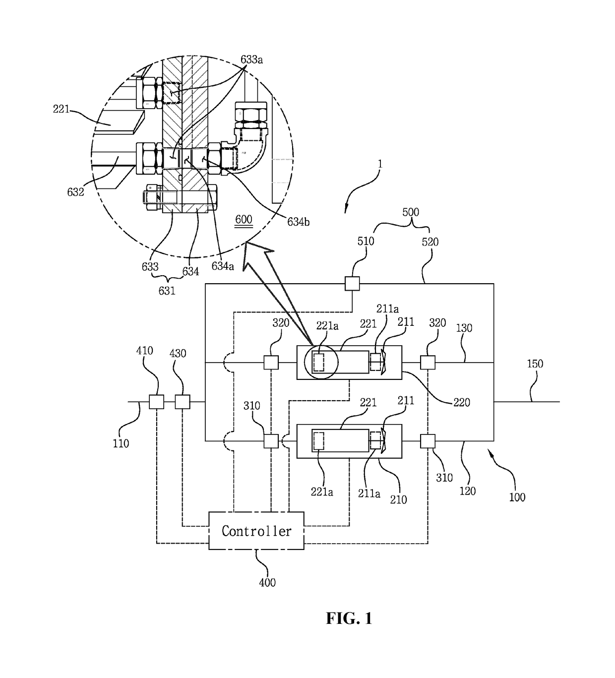
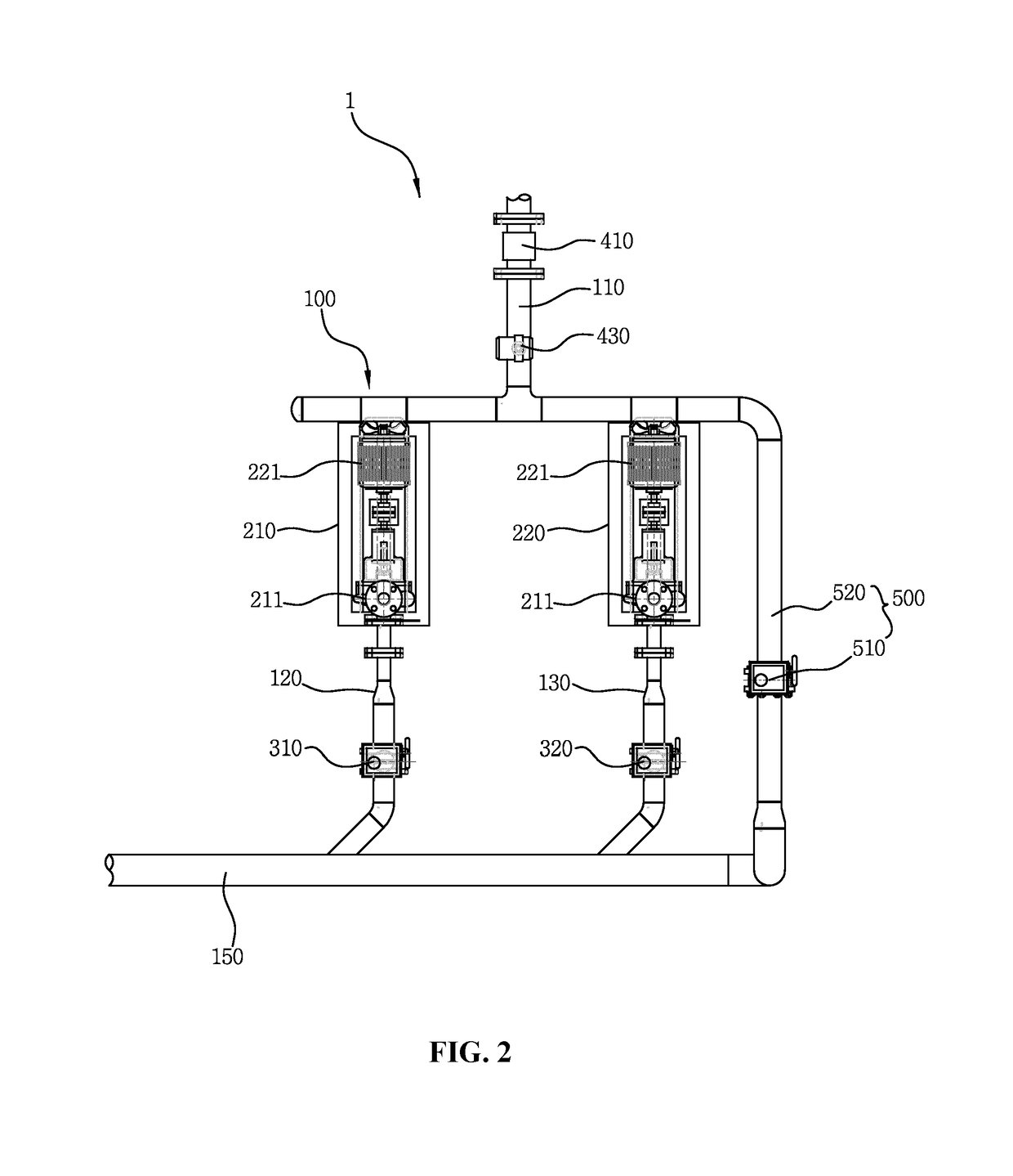
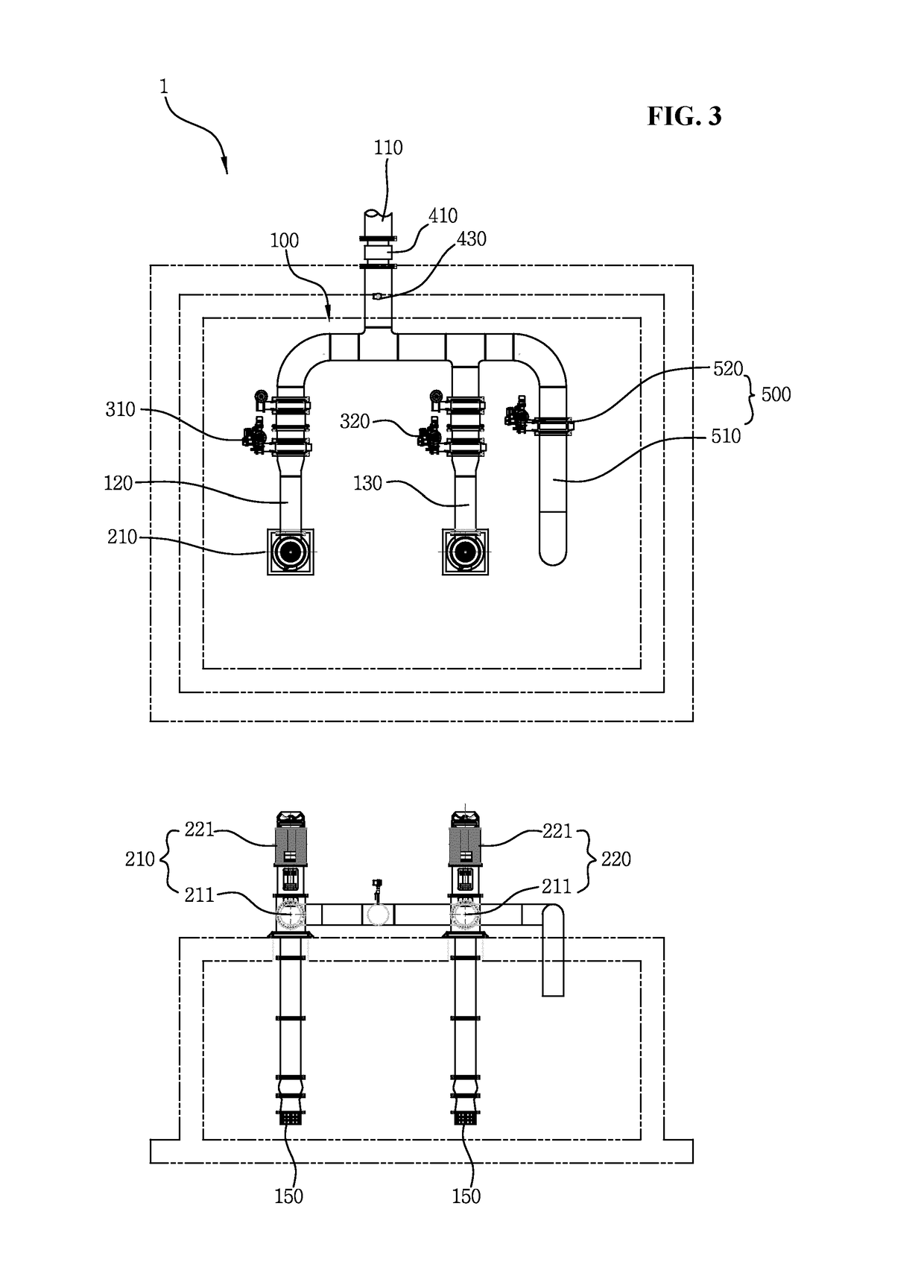
[0016]FIGS. 1 to 8 show a stepwise operating parallel type small hydro power generation system 1 having a fixed flow path 4 according to the present invention.

[0017]According to the present invention, first, the stepwise operating parallel type small hydro power generation system 1 having a fixed flow path largely includes a parallel pipe 100, a first power generation facility 210, a second power generation facility 220, first flow rate regulators 310, second flow rate regulators 320, and a controller ...


PUM


Abstract

A stepwise operating parallel-type hydro power generation system having a fixed flow path includes a parallel pipe, a first power generation facility, a second power facility generation facility, first and second flow regulators, and a controller. The parallel pipe includes an inlet pipe, an outlet pipe, and a first straight pipe and a second straight pipe. The first and second straight pipes connected between the inlet pipe and the outlet pipe. Each of the first and second power generation facilities includes a water turbine rotating with the water introduced thereinto and a power generator operating according to the rotation of the water turbine. The controller is configured to open and close either or both of the first and second flow rate regulators at the same time.

Description

BACKGROUND OF THE INVENTIONField of the Invention[0001]The present invention relates to a stepwise operating parallel type small hydro power generation system having a fixed flow path that is installed on pipes of a water treatment facility or small river to convert kinetic energy using water (pressure and flow rate of water) running along pipes into electric energy and thus to generate and supply electric power.Background of the Related Art[0002]Generally, water power generation is carried out by converting kinetic energy using pressure and flow rate of water produced by the flow of water into electric energy to generate electric power. The water power generation is divided into large capacity water power generation that blocks river or builds a dam to generate electric power through falling water levels of running water and small hydro power generation that is applied to small river, agricultural waterway, and various water treatment facilities and has a generating capacity of les...

Claims


Application Information

Patent Timeline
Patent Type & Authority Patents(United States)
IPC IPC(8): F03B15/12F03B15/18H02P9/04H02P9/10F03B3/18H02P101/10
CPCF03B15/12F03B3/183F03B15/18H02P9/04H02P9/107Y02E10/28H02P2101/10Y02E10/22Y02E10/226F03B11/004F05B2220/20F05B2220/602F05B2220/706F05B2250/82F05B2260/20Y02B10/50Y02E10/20F03B13/08F03B15/005F03B17/06
Inventor YEO, OK KYU
Owner KEUNNAMU
Why Eureka
Try Eureka